Composite material simulation: choosing the right modelling scale
Micro, meso or macro? How to pick the level of detail that answers your design question, and where each level breaks down in stiffness, strength, fatigue and crash work.
Composite material simulation fails most often not because the solver is wrong, but because the model sits at the wrong scale for the question being asked. A laminate that is perfect for a stiffness check can be useless for predicting where a crash structure starts to crush.
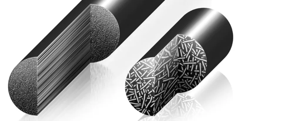
Fibre-reinforced composites are hierarchical. Fibres a few microns across sit in a polymer matrix; bundles of fibres form tows; tows are stacked, woven or braided into plies; plies make a laminate; laminates make a part. Every one of those levels can be modelled explicitly, and every level you add multiplies the cost. The engineering skill is choosing the coarsest model that still captures the mechanism that decides your design.
The three scales of composite modelling
It helps to think of three working scales, each with its own inputs, outputs and blind spots.
| Scale | What is modelled | Typical use | Main limitation |
|---|---|---|---|
| Micro | Individual fibres and matrix in a representative volume element (RVE) | Homogenised ply properties, matrix cracking onset, effect of voids and fibre volume fraction | Far too expensive for parts; needs constituent data that suppliers rarely give |
| Meso | Tows and the weave or braid architecture, or individual plies with cohesive interfaces | Textile stiffness, delamination, damage progression in coupons and sub-components | Mesh and run time grow quickly; architecture must match the real preform |
| Macro | Homogenised plies or a smeared laminate in shell or solid elements | Full-part stiffness, buckling, strength screening, crash and drop at vehicle scale | Cannot see mechanisms smaller than an element unless they are built into the material law |
Micro scale: when the constituents matter
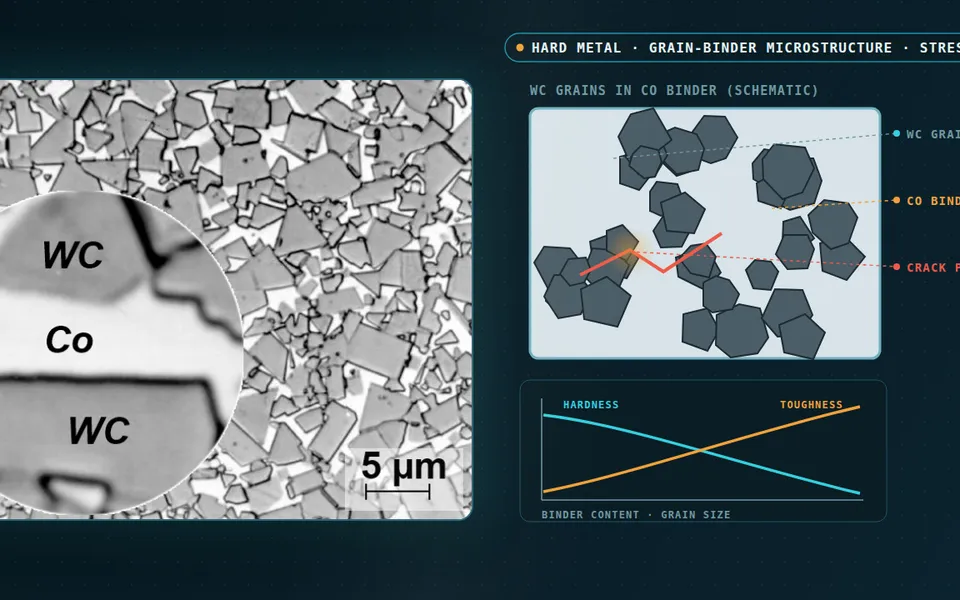
At the micro scale an RVE of fibres and matrix is loaded in each direction to produce effective ply properties. It is the right tool when you are changing the constituents themselves: a new resin, a different fibre volume fraction, or a known void content from manufacturing. It is also how transverse cracking and fibre-matrix debonding can be studied before any coupon exists.
Outside material development, the micro scale is usually a step in the workflow rather than the model that answers the question. Its job is to feed better properties upward.
Meso scale: architecture and interfaces
The meso scale is where textile geometry and ply interfaces live. For braided composites and woven fabrics, the undulation of the tows changes stiffness and strength in ways a flat ply model cannot see. For laminates, cohesive zones between plies are the standard way to predict delamination under impact and at free edges.

Macro scale: parts, assemblies and vehicles
Almost every part-level decision is made at the macro scale: stiffness and frequency targets, buckling, first-ply failure screening, and crash or drop of a full assembly. Plies are homogenised and the physics of damage is represented by the material model rather than by geometry. This is where the choice of failure criterion and damage law dominates the answer.
Failure criteria are part of the scale decision
A macro model is only as good as the failure theory inside it. The long-running World-Wide Failure Exercise showed that no single criterion predicts every laminate and load case well, so the criterion must be chosen for the failure mode that matters.
- Maximum stress or strain: simple and transparent, useful for fibre-dominated loading, but blind to interaction between stress components.
- Tsai-Wu: one smooth interactive envelope, convenient for screening, but it does not say which mode failed.
- Hashin and Puck: separate fibre and matrix modes, which is what a progressive damage model needs to degrade the right stiffness.
- LaRC-type criteria: physically based matrix and kinking modes, well suited to compression-dominated and impact problems.
A rule of thumb
Combining scales in one validated workflow
The most robust programmes link scales instead of choosing one. A typical sequence runs as follows.
- Characterise or homogenise ply properties, from coupon tests where possible and from RVE models where tests are missing.
- Calibrate the damage model on coupons and simple elements: tension, compression, in-plane shear and interlaminar fracture toughness.
- Validate at sub-component level, for example a drop-weight impact to a standard such as ASTM D7136, before trusting the full part.
- Use the macro model for the part, and switch to local meso-scale detail only in the regions that decide the design.
Guidance such as the CMH-17 Composite Materials Handbook sets out the building-block approach behind this sequence: confidence is earned at each level before it is spent at the next.
Where scale choices go wrong
- Using datasheet properties for a part whose real fibre volume fraction and void content differ.
- Expecting a shell model with a smeared laminate to predict delamination it has no way to represent.
- Calibrating damage on one mesh size and running the part on another, which shifts the energy absorbed in crash.
- Ignoring strain-rate effects in impact and crash, where many polymer matrices stiffen and strengthen.
Each of these looks fine in a contour plot and fails in a test. A clear statement of which mechanism the model must capture, and which it deliberately does not, prevents most of them.
Choosing your scale: a short checklist
- What single quantity decides the design: stiffness, first failure, residual strength, energy absorbed?
- Which mechanism controls that quantity, and at what length scale does it happen?
- What test data exists at that scale to calibrate and validate against?
- How many design iterations will the model have to run, and in what time?
If you are planning a composite programme, our composite materials simulation work covers the full chain from ply characterisation to impact, crash and blast, and composites fatigue for parts that must last.