Crash simulation you can trust: building a credible explicit model
Mesh, materials, contact, energy balance and correlation. The checks that separate a crash model that merely runs from one you can sign a design off with.
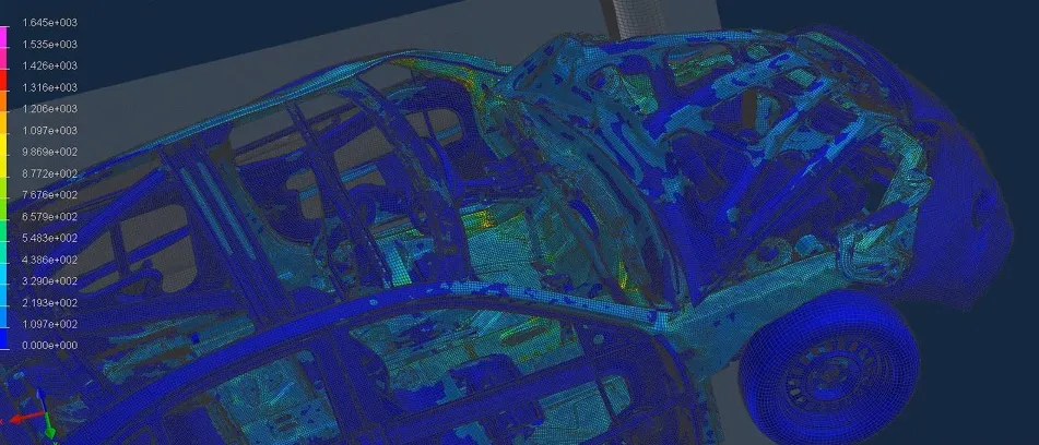
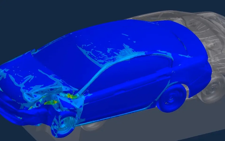
Any explicit solver will turn a mesh into a dramatic deformation plot. The hard part of crash simulation is showing that the plot means something: that peak loads, intrusions and energy absorbed would survive a comparison with a physical test.
Crash models are now used to make decisions long before prototypes exist, from body-in-white structures to seats, battery enclosures and eVTOL airframes. That only works if every model passes the same set of credibility checks. These are the ones we apply on every programme.
Start from the question the test answers
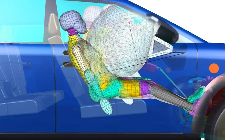
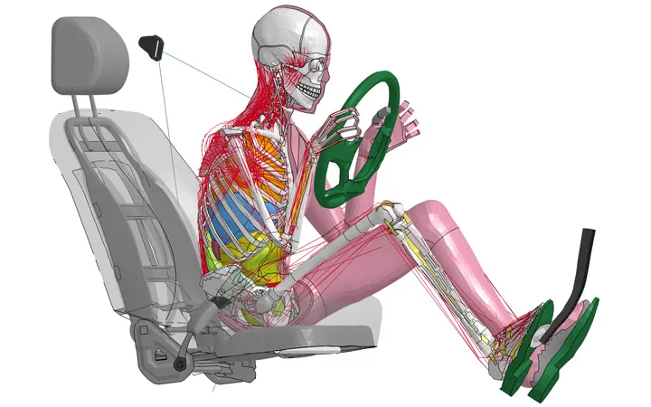
A crash simulation should be set up around the load case and the outputs that the real test or regulation judges: barrier type and speed, occupant or dummy measures, intrusion at defined points, or pulse at a sensor location. Protocols such as those published by Euro NCAP define these precisely. Copying their definitions into the model, including filter classes for accelerations, avoids arguments later about what was compared with what.
Mesh and elements
Explicit crash models use mostly shell elements for sheet structures, with solids for castings, foams and thick sections. Element size is a compromise between capturing folding and keeping the stable time step large enough to run.
- Use a mesh fine enough that each fold of a crushing rail spans several elements; a fold inside one element cannot form.
- Keep element quality under control: very small elements set the time step for the whole model.
- Choose element formulations deliberately and watch hourglass energy where reduced integration is used.
- Represent spot welds, adhesives and rivets with connection models that can fail, because joints often decide the crush mode.
Material data at the right strain rate
Steels, aluminium alloys and polymers behave differently at crash strain rates than in a quasi-static tensile test. Using static curves typically under-predicts the force a structure carries. A credible model uses rate-dependent curves, and for parts that fracture, a failure model calibrated for the mesh size actually used.
The most common credibility gap
Contact definition
Contact is where many crash models quietly go wrong. Parts that should touch pass through each other, or initial penetrations create artificial forces at time zero. A clean model removes initial penetrations, uses a self-contact for folding parts and checks contact energy throughout the run.
Energy balance and mass scaling
The energy report is the single most useful health check of an explicit run. Total energy should be conserved, with kinetic energy converting into internal energy as the structure deforms.
| Check | What to look for | Typical acceptance |
|---|---|---|
| Total energy | Stays nearly constant through the event | Drift within a few percent |
| Hourglass energy | Spurious zero-energy deformation modes | Small fraction of internal energy, often under 5 to 10% |
| Added mass | Mass introduced by mass scaling to raise the time step | Small, and away from parts that decide the result |
| Contact energy | Sliding interface energy | Positive and small; negative spikes point to penetrations |
| Sliding and damping energy | Energy lost to friction or numerical damping | Physically plausible for the event |
Mass scaling is legitimate and widely used to keep run times practical, but added mass must be reported and kept away from the components whose inertia drives the result.

Correlation: proving it against test
Correlation is more than overlaying two curves. It compares timing, peak values, deformation mode and energy absorbed, at the same filtered channels the test used. Build confidence in steps:
- Material and joint coupons, to calibrate the cards.
- Component tests such as a crushing rail or a restraint system sled test.
- Sub-system and full-vehicle tests, where the model is finally trusted to predict what was not measured.
Industry bodies such as NAFEMS publish guidance on simulation credibility and verification and validation; the same principles apply directly to crash.
A short pre-release checklist
- Units consistent and checked on a simple hand calculation.
- No initial penetrations; contact definitions cover every part that can touch.
- Rate-dependent material data, with failure calibrated for this mesh size.
- Energy report reviewed: total, hourglass, added mass and contact energy within limits.
- Outputs filtered and located exactly as in the test or protocol.
- Correlation documented at coupon, component and system level.
Our crash test simulation team applies these checks across automotive, seats and aerospace, including small overlap and oblique impacts and airbag effectiveness.