Brazing simulation for joint gap, furnace cycle and residual stress
A brazed joint leaks in one corner of the load, or a ceramic cracks on cooling. Coupling a furnace thermal model to a structural model of thermal-expansion mismatch shows the gap at temperature, the coldest joint and the stress the assembly keeps, before the next trial load.
Brazing simulation predicts three things before the next load goes into the furnace: whether the filler fills the joint gap, whether every joint reaches temperature, and what stress the assembly keeps after it cools. We build that chain, a furnace thermal model feeding a structural model of thermal-expansion mismatch, as a workflow your engineers run on the thermal-structural solver you already use.
A brazed assembly comes out of the furnace and fails its leak test in one corner of the load. The gap on the drawing was in tolerance, the filler is the specified alloy and the furnace profile ran as set. Now the choice is to scrap the load, re-braze it in a second cycle with its own risks, or change the fixture, the load layout or the gap and spend a furnace cycle on a trial. For a ceramic-to-metal joint the same question arrives as a cracked ceramic on the first article.
What does a brazing simulation have to answer?
Three questions, in the order the joint lives them. Does the molten filler reach the whole gap? Does every joint in the load stay above the filler's melting range for long enough, with no part overheating? And what stress does the assembly lock in as it cools? TWI defines brazing as joining with a filler whose melting point is above 450 °C and always below that of the parts.
One cause sits under all three: dissimilar metals, or a metal and a ceramic, expand and contract by different amounts. The mismatch changes the gap while you heat and sets the stress after you cool, and the furnace decides how unevenly it acts.
Why is the joint gap the design variable in brazing?
Capillary pressure pulls the filler in, and it depends on the gap. For a filler of surface tension γ wetting parallel faces a distance g apart at contact angle θ, the pressure is Δp = 2γ cosθ / g. A narrower gap pulls harder and resists flow harder: with viscosity μ, and neglecting gravity, the fill length follows L2 = γ g t cosθ / 3μ. TWI notes that the required gap depends on many factors, among them the atmosphere and the compositions of the base material and the braze alloy.
The gap that counts is the gap at brazing temperature. For a pin of radius r in a socket of another metal, the radial gap becomes g = g0 + (αB − αA) r ΔT, with B the socket and A the pin. A socket that grows more opens the gap as it heats, one that grows less closes it. Contact angle and viscosity move with atmosphere, flux, oxide film and temperature, so a flow model takes them from your own tests.
- Filler at the mouth. A ring, foil or paste of filler sits at the entrance of the joint. When the load passes the filler's melting range it becomes liquid, and what draws it into the joint is capillary pressure.
- Capillary front. The liquid advances while it wets the walls. For parallel faces the pressure is Δp = 2γ cosθ / g, and viscous resistance slows the front, so that without gravity the fill length follows L² = γ g t cosθ / 3μ. Atmosphere, flux, oxide film and temperature change θ and μ.
- The gap. A narrower gap pulls harder and resists flow harder; a wider gap fills faster and holds the filler with less force. The right value depends on the filler, the base metals and the atmosphere, so it is a design variable to calculate, not a constant to copy.
- Voids. Where the front stalls or an oxide film is not wetted, the joint keeps a pocket. A cold corner that never reached the melting range is one cause the thermal model can find; wetting problems must be seen in test sections.
- Gap at temperature. The two parts are different metals and grow by different amounts. For a pin of radius r in a socket, g = g0 + Δα r ΔT, with Δα = αB − αA. The gap that fills the joint is the gap at brazing temperature, and it can open or close.
How is brazing usually designed, and where does that break?
Usual practice takes the gap from the filler supplier, runs a trial load with thermocouples on a few parts, and proves the joint by leak test, section and pull test. AWS C3.6M/C3.6:2026 classifies furnace-brazed joints by loading and the consequence of failure, with quality-assurance criteria for each class. Three things break the practice beyond its range.
- The gap at temperature. The room-temperature gap is checked. For dissimilar metals the gap at the melting range is not.
- The load, not the part. Nadolny, Rogalewicz and Hamrol measured temperatures inside aluminium heat exchangers in a continuous controlled-atmosphere furnace. Heat arrives by convection, conduction and radiation, in proportions that depend on the type and mass of the load, and jigs are crucial at the elevated temperatures where radiation begins to outweigh convection.
- A peak stress that moves with the mesh. An elastic ceramic-to-metal analysis puts its largest stress at a free edge, where the number depends on element size.
| Question | What drives it | What the model resolves | Decision it supports |
|---|---|---|---|
| Starved or voided joint | Gap at temperature, wetting, a cold corner | Furnace thermal field plus capillary fill in the real gap | Gap, fixture and load layout before a trial load |
| Core or stack in a furnace | Load mass, jigs, radiation against convection | Load thermal model with radiation and jig mass, calibrated to thermocouple traces | Profile and jig material, so every joint melts the filler together |
| Dissimilar metals, sleeve and pin | Expansion mismatch that opens or closes the gap | Gap at temperature, then cooling stress with filler plasticity | Fit and clearance, filler and geometry |
| Ceramic or carbide to metal | Mismatch on cooling, edge singularity, layer thickness | Elastic-plastic cooling analysis with a statistical fracture measure | Interlayer, layer thickness, bonded area, cooling rate |
| Joint strength in service | Thin constrained layer, overlap, imperfections | Joint model calibrated on lap, butt and button specimens | Overlap and design allowable |
How do you simulate the furnace cycle and its temperature uniformity?
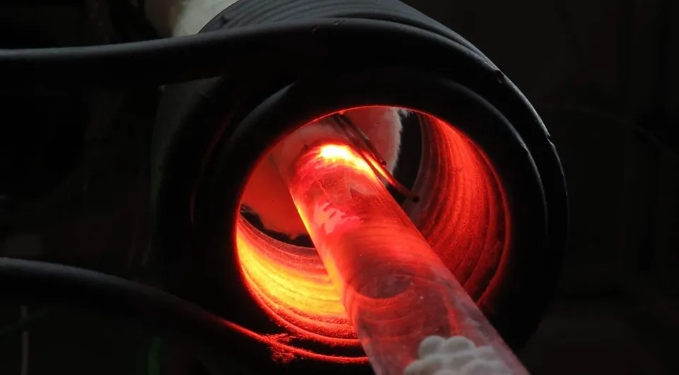
Heat reaches an assembly by radiation, gas convection and conduction through its own parts and fixtures. Radiation between a surface at Ts and walls at Tf carries q = εσ(Tf4 − Ts4), so surfaces that see the walls heat far faster than surfaces shielded by their neighbours. Conduction lags by a time that scales as L2/a, thickness squared over diffusivity, so heavy sections and heavy jigs follow the furnace slowly. The result is a cold corner of the load, and the joint in it is the last to reach the filler's melting range.
We model the load thermally in LS-DYNA, Ansys, Abaqus, Comsol, Simufact Welding or your existing thermal-structural solver, including radiation exchange and jig mass. Where gas flow matters, a CFD model of the furnace supplies the convection and radiation boundary conditions, and a thermocouple trace from a real load calibrates emissivities and contact conductances. The check is set before the run: every joint above the filler's melting range for the time your procedure requires, and no part above the limit your materials set. Our heat exchanger article covers plate-fin context.
How do you predict residual stress and joint strength after brazing?
On cooling the filler solidifies and the joint starts to carry load. From that temperature, Ts, the mismatch is locked in: Δε = (α1 − α2)(Ts − T0). Times a modulus it gives an elastic estimate that overshoots wherever the filler or the metal yields, so the model carries plasticity through the cooling cycle.
In ceramic-to-metal joints the critical number sits at the edge. TWI's summary of its member report 852/2006 states that the mismatch generates high residual stresses during cooling, that very high stresses, increasing as the braze gets thinner, build up at the joint edge and may fracture the ceramic, and that conventional stress analysis did not correlate clearly with observed failure. Park, Mendez and Eagar describe the cause: at the periphery of the ceramic the elastic stress is a singularity, σ = H r−λ, with an exponent specific to the material pair, so a peak stress alone cannot explain the fracture. The route TWI examines is a Weibull fracture model fed by finite element analysis of the brazing cycle and calibrated by experiment. Park and colleagues also note that ductile interlayers relieve residual stress.
For metal-to-metal joints a thin filler layer between stiffer parts is constrained, so its stress state and apparent strength differ from a bulk specimen of the filler. We calibrate the joint model on the specimens AWS C3.2M/C3.2:2019 describes for brazed-joint strength: single-lap shear, butt-tension and, for ceramics, the tensile button.
- Furnace and exposed edge. Surfaces that see the furnace walls heat first, by radiation and gas convection, and cool first. This curve follows the furnace profile closely.
- The cold corner. A heavy section, a shielded joint or a massive jig lags by a time that scales with thickness squared over diffusivity. It crosses the melting line late and leaves it late, so every joint in the load is checked against its own history.
- Solidification. On cooling, the filler freezes as each joint passes its solidification temperature. From there the joint carries load and the expansion mismatch is locked in. Joints in different parts of the load freeze at different times.
- Contraction mismatch. Between solidification and room temperature the metal contracts more than the ceramic. The thermal strain mismatch is Δε = (αm − αc)(Ts − T0). The elastic estimate overshoots where the filler or the metal yields.
- Stress at the free edge. At the periphery of the ceramic the elastic stress is singular, σ = H r^−λ, so its peak depends on the mesh. A Weibull-type failure measure, calibrated on test joints, replaces the peak as the strength metric.
- Braze layer and interlayer. Layer thickness and a ductile interlayer are the design levers: a thinner braze raises the edge stress, and an interlayer relieves stress at the cost of another material in the joint.
A predicted stress is not a qualified joint
Where does AI help brazing simulation, and where does it not?
- Load screening. A thermal model run over planned variations of load layout, jig mass and profile trains a surrogate that returns the temperature margin of the coldest joint in seconds, and a failed run never enters the training set. See surrogate models for CFD and FEA.
- Calibration with uncertainty. Emissivity, contact conductance and wetting parameters are fitted to thermocouple traces and sections, and the model reports a band, not a single curve.
- Edge-stress ranking. A model trained on cooling-stress runs ranks geometry, layer thickness and interlayer options, and sends unusual geometry to the full analysis.
It does not predict wetting on a surface it has not seen, the oxide film or flux behaviour that decides whether a filler wets, or a void in a joint nobody sectioned. Each surrogate has a stated range, and outside it the request goes to the full model. For thermal cycling in service, see our thermomechanical fatigue article.
From one troublesome joint to a brazing capability you keep
The return comes when the next part number goes through the same chain without a new trial load.
- Physics model. CFD and FEA set up once, as templates: geometry clean-up, mesh, solver settings and post-processing that every later run reuses.
- Validation. Mesh and time-step studies, and comparison with tests or full-scale data, so the model's uncertainty is known before it is trusted.
- Automated runs. Scripted runs over the parameters and operating conditions that matter, on your hardware or in the cloud.
- AI surrogate. A machine-learning model trained on those runs answers in seconds and says how sure it is; low-confidence questions go back to the solver.
- Decision tool. Optimisation, trade-off charts or operating guidance, in a form your engineers and operators use every day.
- Field data. Test, trial and monitoring data flow back to recalibrate the model, so it improves with every project instead of being rebuilt.
- A joint file holding materials, filler, gap, overlap and layer thickness: a new joint is a line of input.
- A furnace-load template in your thermal solver, calibrated to your thermocouple traces, reporting the temperature margin of every joint.
- A cooling-stress template that carries the filler's plasticity from solidification, with the edge measure agreed before the run.
- A validation record built on your last trial load: sections, tests and tolerances set before the run.
- A surrogate with a stated range and a gate at its edge, so a request outside it goes to the full chain.
- Handover and training, so your team extends it itself. See our training and software development services.
Questions engineers ask about brazing simulation
What is the right joint gap for brazing?
Can finite element analysis predict whether the filler will fill the joint?
Why do ceramic-to-metal brazed joints crack on cooling?
Is distortion in brazing different from distortion in welding?
Can simulation replace brazing procedure qualification or testing?
If a brazed joint is leaking, cracking or waiting on a trial load, send us the joint drawing with materials and filler, the furnace profile and load layout with any thermocouple traces, and the test or section results you have. We reply with how we would model the gap at temperature, the furnace load and the cooling stress, which measurements the validation record needs first, and how your team would run it afterwards. Start with a conversation. The welding simulation hub and its brazing simulation page set the wider context.