Heat exchanger design beyond correlations: what CFD, FEA and AI add to the rating
Kern, Bell-Delaware and e-NTU get a heat exchanger sized. Maldistribution, new surfaces, vibration, thermal stress and fouling decide how it performs. How unit-cell CFD, porous models, FEA and surrogates close the gap before the test does.
Heat exchanger design starts with a rating method, e-NTU or LMTD with correlations such as Kern, Bell-Delaware or Colburn j and Fanning f, and needs CFD where those correlations stop applying: uneven flow distribution, new geometries and mixed flows. We use conjugate CFD, FEA and surrogate models to close that gap, so duty, pressure drop and life are known before the unit is built.
The exchanger sets the size, weight, cost and efficiency of what surrounds it, whether that is a heat pump, a process train, a power or hydrogen plant or a cooling loop. When it falls short on test, every remedy is expensive: more surface, a larger pump, a derated product, or a redesign after tooling. So the design-review question is rarely "does the correlation say it works?". It is whether this unit will deliver its duty at an acceptable pressure drop and still do so after years of fouling and vibration.
What do heat exchanger correlations assume?
The rating calculation is compact: Q = U·A·F·ΔTlm, or equivalently ε = f(NTU, Cr) with NTU = UA/Cmin. The effort goes into U, which adds the hot-side coefficient, the wall, the fouling resistance and the cold-side coefficient, and into the pressure drop. For shell-and-tube units, Kern's method and the more detailed Bell-Delaware method estimate the shell-side coefficient and pressure drop from an ideal tube bank, corrected for baffle-window flow, leakage and bypass streams. For compact plate-fin and printed surfaces, each surface is tabulated as a Colburn factor, j = Nu/(Re·Pr1/3), and a Fanning friction factor, f, against Reynolds number.
These methods are fast and traceable, and inside their database they are right. They assume steady single-phase flow shared evenly between parallel passages, a fixed set of corrections for leakage and bypass, properties that vary little through the unit, and a surface close to the one that was tested. Standards sit around this calculation. The TEMA Standards are, in the association's words, specified by industrial plants worldwide, and its page announces a 2026 edition. ASME BPVC Section VIII Division 1 covers the design, fabrication, inspection, testing and certification of pressure vessels operating above 15 psig. ISO 16812 specifies mechanical design, materials, fabrication, inspection and testing of shell-and-tube exchangers for the petroleum, petrochemical and natural gas industries, and supplements API Std 660. They govern how the unit is built. The thermal rating still rests on the correlations above.
Where do heat exchanger correlations stop being reliable?
Five situations recur, and the drawing shows where most of them live.
- Header and tube-side distribution. A single nozzle feeds the channel head as a jet, so the central tubes see more flow than the outer ones. The tube-side coefficient then varies from tube to tube, not just along them.
- Baffle cross-flow. Segmental baffles steer the shell-side fluid across the bundle and through the windows. Correlations treat this as an ideal tube bank corrected for the window flow; CFD shows the actual path and its pressure drop.
- Dead zones and leakage. Fluid stalls in the corners behind the baffles, and part of the flow bypasses the bundle through the tube-baffle and baffle-shell clearances instead of crossing it. Both lower the effective area and change with manufacture and wear.
- Tubesheets and joints. The tubesheet ties tube and shell together, so differential expansion and start-up or trip transients load the tube joints. FEA needs the temperature field that CFD can supply.
- Unsupported tube spans. Tubes in a baffle window are supported only at every second baffle, and inlet and outlet regions see high local velocity. Those spans are where fluidelastic instability and vibration wear start.
- Fouling. Deposit adds a thermal resistance R_f that grows with time, and narrows the flow area, so duty falls and pressure drop rises over the life of the unit.
- Maldistribution. Real headers do not feed parallel passages equally; a jet from the nozzle loads the central tubes or channels. Li et al. (2023) in Applied Thermal Engineering studies the effect of single-phase flow maldistribution on the thermal performance of brazed plate exchangers.
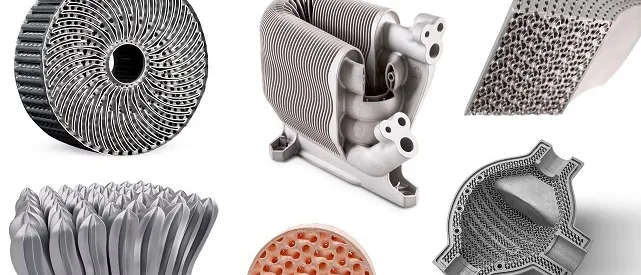
- New geometries. Printed-circuit, lattice and additively manufactured surfaces have no published j and f, and as-built roughness differs from the drawing.
- Mixed and complex flows. Baffle leakage, bypass, cross-counterflow arrangements and strongly temperature-dependent properties push a unit outside the correction factors.
- Local extremes. The wall temperature peak that starts fouling, boiling or thermal fatigue is not in an area-averaged U.
- Phase change. Boiling and condensation coefficients depend on flow regime, vapour quality and surface condition, so the uncertainty is wider than in single-phase flow.
What does CFD add to heat exchanger design?
Conjugate heat transfer solves conduction in tubes, fins, plates and tubesheets together with convection in both fluids, so wall temperature is a result, not an assumption. On a full unit it shows how flow divides between passages, the shell-side path around the baffles with its dead zones and leakage, the hot and cold spots in the wall, and where the pressure drop is spent: in the core, or in the nozzles, headers and windows. It does not replace the rating. It adds what the rating cannot see. Resolving every tube of a full unit is out of reach for most projects, so the work is organised as a hierarchy.
How do unit-cell and porous-media models make full-size CFD affordable?
The scale gap is the difficulty: features of a fraction of a millimetre to a few millimetres, repeated thousands of times, in a unit metres long. Two models bridge it. A unit-cell model resolves one repeating element of the surface, such as a pin-fin cell, an offset-strip period or one printed channel bend, with periodic boundaries and a prescribed flow. Run over a range of Reynolds number, it gives j and f for a surface nobody has tabulated, including the wall conduction and, for printed parts, the as-built roughness. A porous-media model then represents the core as a distributed resistance, a momentum sink of the form −(μ/α)u − C2(ρ/2)|u|u, together with a volumetric heat exchange built from the unit-cell j and f. Headers, nozzles, baffles and the full pressure field are resolved at the cost of a coarse mesh.
- Correlation. e-NTU or LMTD with j and f from published surfaces. Fast and traceable, and right when the surface is known and the flow is evenly distributed.
- Unit-cell CFD. A periodic cell of the actual surface, a fin, pin array or printed channel, run over a range of Reynolds number to produce j and f where no correlation exists.
- Porous full-size model. The core is represented by a distributed resistance and a volumetric heat exchange taken from the unit cell, so headers, nozzles and baffles can be resolved at full size at modest cost.
- Surrogate and optimiser. A model trained on planned unit-cell and full-size runs returns j, f or duty and pressure drop almost instantly, so a multi-objective search can run over geometry.
- FEA and life checks. The temperature field, local gap velocities and fouling allowance leave the thermal-hydraulic model for thermal stress, vibration and degradation checks.
- Test data and gate. Bench or plant data calibrate the uncertain inputs. The surrogate reports when a request is outside its training range, and that request goes back to CFD.
Each level needs its own verification: the unit cell against surfaces whose j and f are known, the porous core against a resolved sub-model, the full model against test. The limits are real. A periodic cell misses developing flow near the entry and strongly unsteady shedding, and an isotropic porous core misses cross-flow inside the bundle unless it is made anisotropic.
| Model | What it resolves | Use it when |
|---|---|---|
| e-NTU or LMTD with correlations | Duty and mean pressure drop for a known surface and even flow | Sizing, ratings, early trade-offs |
| Unit-cell CFD | j and f of a repeating surface, with wall conduction | The surface is new, printed, or outside published data |
| Porous-media full-size CFD | Header, nozzle and baffle flow, distribution, total Δp | Maldistribution or layout is in question |
| Resolved conjugate CFD of a section | Local wall temperature, hot spots, recirculation | A local extreme drives fouling or stress |
| FEA with the CFD fields | Thermal stress, tubesheet and joint loading, vibration modes | The thermal and flow fields set a structural margin |
What decides the real outcome: pressure drop, vibration, thermal stress and fouling?
The thermal-hydraulic trade-off. Every gain in the heat-transfer coefficient costs pressure drop, and pumping power is QΔp/η. A common screen compares surfaces at equal pumping power with (Nu/Nu0)/(f/f0)1/3 against a reference. It is a screen, not a verdict, because it ignores mass, cost and fouling.
Flow-induced vibration. Tube-bundle vibration is a coupled problem of local flow, damping and tube dynamics. The two-part overview by Pettigrew and Taylor in the Journal of Fluids and Structures covers flow, damping and fluidelastic instability (Part 1) and vibration response, fretting wear and guidelines (Part 2). For design, the risk sits in local velocities at the inlet, in baffle windows and across unsupported spans, which an area-averaged rating does not give. CFD supplies the velocity field and FEA the modes. See our thermal FSI and vibration fatigue work.
Thermal stress. Tubes and shell run at different temperatures and expand differently, and the tubesheet ties them together. Start-up, shutdown and trips load the tube joints. The pressure-vessel codes give design rules; where loading is transient or geometry unusual, the CFD temperature field becomes the thermal load for FEA. See thermal stress simulation.
Fouling. Deposit adds a resistance Rf(t) to 1/UA and narrows the flow area, so duty falls and pressure drop rises with time. A common model balances deposition against removal and gives an asymptotic Rf that depends on velocity and wall temperature. A fixed allowance is a guess about that curve, and extra surface lowers velocity, which for many fluids makes fouling worse. Design the margin and the cleaning interval from the curve.
Do not size on the clean, even, steady-state case
How does AI help heat exchanger optimisation, and where does it not?
- Surrogates of j and f over geometry. Trained on a planned set of unit-cell CFD runs, they return j and f for a new geometry and Reynolds number almost instantly, with a stated uncertainty. See surrogate models for CFD and FEA.
- Multi-objective optimisation of duty, pressure drop, mass, cost and manufacturability, with process limits such as minimum wall, powder removal and overhang as hard constraints. The result is a Pareto front to choose from. See generative design and optimisation.
- Calibration against test data, tuning the uncertain inputs (leakage, roughness, fouling resistance) and exposing where the model is wrong. See hybrid physics-AI modelling.
- A solver gate. When a request falls outside the training range or the surrogate is unsure, it goes back to CFD. See AI surrogate models you can sign off.
Where AI does not help: a surrogate inherits every error of the CFD that trained it and knows nothing outside its envelope. Phase change is the clearest limit. Interface-resolving multiphase CFD is not practical at exchanger scale, so boiling and condensation enter as calibrated sub-models inside the porous or network model, with wider uncertainty and a firm need for test data. See our multiphase flows page. For printed surfaces, the as-built shape and roughness matter; additive manufacturing simulation covers distortion, and cold-plate CFD shows the same chain for electronics.
From one exchanger study to a design capability you keep
A single study answers the question it was asked. The larger return comes when the set-up becomes a workflow your own team runs, so the next geometry or duty question costs hours, not weeks, and every answer is checked the same way. That is how we build heat exchanger work.
- Physics model. CFD and FEA set up once, as templates: geometry clean-up, mesh, solver settings and post-processing that every later run reuses.
- Validation. Mesh and time-step studies, and comparison with tests or full-scale data, so the model's uncertainty is known before it is trusted.
- Automated runs. Scripted runs over the parameters and operating conditions that matter, on your hardware or in the cloud.
- AI surrogate. A machine-learning model trained on those runs answers in seconds and says how sure it is; low-confidence questions go back to the solver.
- Decision tool. Optimisation, trade-off charts or operating guidance, in a form your engineers and operators use every day.
- Field data. Test, trial and monitoring data flow back to recalibrate the model, so it improves with every project instead of being rebuilt.
- A parametric template. Geometry, mesh, conjugate set-up and post-processing for the core, headers, nozzles and baffles, with your mechanical and manufacturing limits written in as constraints.
- A validation record tying the unit-cell and full-size models to your test or plant data, with mesh studies and a stated uncertainty.
- Automated runs over flow, inlet conditions, fouling state and geometry, on your hardware or in the cloud.
- A j and f library and a surrogate, in the form your rating tool or system model reads, with their limits and a solver gate.
- A structural hand-off: temperature fields and local velocities passed to your FEA for stress and vibration checks, with the mapping scripted.
- Training and handover, so your engineers can extend the workflow themselves. See our training and software development services.
Questions engineers ask about heat exchanger design and CFD
How do you design a heat exchanger?
Is CFD better than Kern or Bell-Delaware?
What is a porous-media model of a heat exchanger?
Can CFD predict fouling?
What do you need from us to start?
Our heat exchanger simulation work, the wider thermal analysis practice and our process heat-transfer equipment page cover this ground. If a rating, a layout or a surface is on your desk, send us the datasheet, the operating cases and what you have measured. We will reply with how we would build the model, which data would validate it, and what the first results would let you decide. Start with a conversation.