Friction welding simulation for rotary, linear and friction stir joints
A new part changes the heat balance of a friction weld, and every correction costs a forged preform and a sectioned weld. One model of interface heat, large deformation and residual stress, with a surrogate over the process window, shows the right schedule before the next trial.
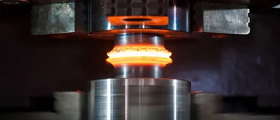
Friction welding simulation predicts how a rotary, linear or friction stir weld heats, deforms and cools: the interface temperature, the flash, the material flow and the residual stress left in the part. We build it as a workflow your engineers rerun on their existing solvers, with a surrogate that maps the process window and a validation record you can put in front of your customer.
The weld that passed on the test bar does not pass on the new part. The diameter, the wall or the second material has changed, the heat no longer reaches the middle of the interface, and the schedule that gave a clean flash now gives a cold core or a burnt rim. Each correction costs a forged preform, a sectioned weld and days on the machine. A dissimilar joint is harder still: the thin reaction layer that governs its strength cannot be seen without cutting the part.
What does friction welding simulation have to predict?
TWI describes rotary, linear and friction stir welding as solid-state processes: the metal softens and is expelled or mixed, not melted. The model has three jobs. It gives the temperature history, which decides the bond, the softened zones and any brittle phase. It gives the deformation, meaning burn-off, flash and material flow, which decides whether the original surfaces are swept out. And it gives the residual stress and distortion that feed the fatigue assessment of the part.
The model differs by process. A rotary weld of a bar or tube is axisymmetric, so a two-dimensional model carries most of the physics. Linear welding is not axisymmetric. A friction stir weld needs three dimensions and the tool motion, although a transverse section answers many questions alone.
Why is a friction weld harder to simulate than an arc weld?
There is no moving heat source to prescribe. The heat comes from the process itself, and it depends on the state of the metal it is heating. At the interface of a solid bar the sliding speed is ωr, so with a friction coefficient μ and contact pressure p the local heat flux is q = μ p ω r, and the total over a bar of radius R at uniform pressure is (2/3) π μ p ω R3. The axis gets nothing at first and the rim gets the most, so the centre is heated by conduction and flow. Once the layer softens, the contact moves from sliding towards sticking and more of the heat comes from shearing it, a volumetric source qv = β σeq dεeq/dt, where β is the fraction of plastic work that becomes heat. In friction stir welding both sources act at the shoulder and around the pin.
Then comes feedback. As the metal heats its flow stress falls, which lowers the shear that makes the heat and lets the axial force push softened metal out as flash. In inertia welding even the rotation speed is a result, because the flywheel obeys J dω/dt = −T, with T the torque at the interface. The friction coefficient is not constant at these temperatures and speeds, so it is a calibration target, not an input.
The deformation is just as demanding. Flash, burn-off and the sweeping of oxide from the original surfaces are large, localised plastic flow, which breaks a conventional finite element mesh. The Materials review of friction stir welding simulation lists intricate coupling between heat transfer and mechanics, very high strain rates and the need to track material flow among the difficulties. Our hot forging article meets the same mesh problem in a neighbouring process.
- Two workpieces, one interface. One piece rotates against a fixed piece under axial force. In direct drive, speed and force are inputs. In inertia welding the flywheel energy is the input and the speed decays as the interface works, so rotation speed is a result of the model.
- Heat grows with radius. The sliding speed at the interface is the angular speed times the radius, so the friction heat flux is zero on the axis and largest at the rim. The model starts hot at the edge and cold at the centre, and conduction and flow fill in the middle.
- The softened layer. Friction and plastic work soften a thin layer on both sides of the interface. It behaves as a viscoplastic solid whose strength falls with temperature. Outside it sit the thermo-mechanically affected and heat-affected zones that a macro-section shows.
- Flash and burn-off. The axial force squeezes softened metal out as a flash collar, and the pieces shorten by the burn-off distance. This is the large, localised deformation that tangles a conventional mesh, and the reason for remeshing, ALE, Eulerian or particle formulations.
- Contaminants leave with the flash. Oxide films and foreign particles on the original surfaces are carried outward into the flash during burn-off. Clean metal then meets clean metal, so a sound bond needs enough softened flow as well as enough temperature.
- The heat chain and its feedback. Friction heat and plastic work soften the interface, and the softening changes both heat sources and speeds the squeeze-out. A fixed heat input cannot represent that loop, so the model carries it explicitly.
How are friction welds usually simulated, and where does that break?
Five formulation families cover most work, and each trades one weakness for another. A Lagrangian model follows the material but needs repeated remeshing at flash-scale deformation. An ALE model lets the mesh move independently of the material and smooths it to limit distortion. An Eulerian or Coupled Eulerian-Lagrangian model lets the material flow through a fixed mesh, which removes tangling but blurs free surfaces. CFD treats the metal as an incompressible viscoplastic fluid heated by viscous loss, with a rigid tool. Particle methods such as SPH drop the mesh, and the review notes that particles tend to cluster. Four problems recur.
- Material data at the extreme. Flow stress at very high strain rate and temperature, and a friction law that changes with contact state, are the largest unknowns.
- One weld at a time. A coupled large-deformation run is expensive, so teams simulate the best-guess schedule, not the window around it.
- Mesh-driven noise. In one study the review describes, force fluctuations were blamed on intermittent node contact and heavy remeshing, and predicted forces ran above the measured ones.
- A hand-off done by hand. The thermal history is copied into a structural model for the residual stress, and every change restarts the chain.
| Process or question | What the model must resolve | Formulation that fits | Decision it supports |
|---|---|---|---|
| Rotary weld, direct drive or inertia | Heating that grows with radius, burn-off, flash, speed decay | Axisymmetric model with remeshing or ALE | Speed, force and burn-off for a new diameter or wall |
| Linear weld of a blade or preform | Oscillating contact, flash, contaminant expulsion | ALE or particle model | Frequency, amplitude, force, burn-off |
| Friction stir butt or lap weld | Flow around the pin, stir-zone temperature, tool forces | CFD-type, ALE or Eulerian stir-zone model | Tool geometry, speed pair, plunge, clamping |
| Dissimilar-metal joint | Interface thermal history, lopsided flow, reaction layer, expansion mismatch | Process model plus diffusion and thermal-structural stages | Peak temperature ceiling, time at temperature, joint design |
| The finished part | Residual stress and distortion | One-way thermal-structural model fed by the process model | Straightening, machining allowance, fatigue input |
How do you map a process window, and what changes in a dissimilar joint?
The parameter list is short, which helps. NASA's 2003 paper on the Space Shuttle External Tank weld machines counts five process variables for the friction stir weld against seventeen for the variable polarity plasma arc process it replaced. In rotary welding they are speed or flywheel energy, force and burn-off. In friction stir welding, rotation speed, travel speed, plunge setting and tool geometry. A planned set of runs across them returns a map: which combinations reach bonding temperature, which squeeze out too much metal, which stay cold. Our welding simulation hub and its pressure welding page set the wider context.
A dissimilar joint adds two mechanisms. The first is a brittle reaction layer between the metals. Where diffusion controls it, its thickness follows x2 = k t with k = k0 exp(−Q/RT), so the interface's thermal history, not its peak temperature alone, sets the layer. TWI notes that rotary friction welding has lower peak temperatures than fusion welding, which reduces intermetallic formation and allows a range of dissimilar materials to be joined, aluminium to titanium or stainless steel in tubular transition joints among them. The second is expansion mismatch: on cooling the metals contract by different amounts, a strain of εth = (α1 − α2) ΔT that the joint geometry turns into residual stress. The softer metal also does most of the deforming, so flash and bond line are lopsided and the model needs the flow stress of both.
- Tool, force and clamping. A rotating, non-consumable tool with a shoulder and a profiled pin is plunged into the joint and traverses along it. The plates are held hard against a backing plate, because the process needs a large down force and traverse force.
- The stir zone. Shoulder friction and plastic work around the pin heat the metal, and it flows around the pin as a viscoplastic material and is mixed. The advancing side, where the tool surface moves with the travel direction, flows differently from the retreating side. This is the zone that CFD, ALE, Eulerian or particle models resolve.
- Affected zones. Beyond the stir zone, the thermo-mechanically affected zone is deformed but not recrystallised, and the heat-affected zone is only heated. Their extent depends on material and process conditions, so the model's zone boundaries can be compared with a macro-section of a trial weld.
- The process window. For each rotation speed there is a range of travel speeds that gives a sound weld, so the window is a band, not a point. Its position and width depend on the alloy, the tool and the thickness, which is why it is mapped for your joint rather than read from a table.
- Too cold and too hot. Too little heat per unit length leaves the metal too stiff to flow around the pin, and voids or a lack of bond become likely. Too much softens a wide zone, raises flash and tool wear. Which side a trial fell on is confirmed by sectioning and testing, not by the model alone.
- Planned runs and a surrogate. A planned set of simulations samples the parameter space, and a surrogate fitted to them maps temperature, force and zone size across the band, with a stated range. The nominal point carries an uncertainty ring, because material data and the friction law are uncertain, and runs near an edge go back to the full model.
Where does AI help friction welding simulation, and where does it not?
- A surrogate over the window. Trained on planned runs of the physics model, it returns peak interface temperature, torque, burn-off rate, flash size and key residual stresses across the parameter space in seconds, with a stated range and its uncertainty. See AI surrogate models you can sign off.
- Calibration. A few coefficients carry most of the uncertainty: the friction law, the flow-stress constants and the heat loss into tooling. Fitting them to measured torque, temperature and burn-off curves is an inverse problem that machine learning handles well, and it returns a spread, not a single value.
- Run triage. Energy-balance, mesh-quality and contact checks run on every job, so a run with a collapsed mesh never reaches the training set.
AI does not know whether a weld is sound. A void, a lack of bond or a brittle layer is confirmed by sectioning and testing, and a classifier on simulated temperatures is only as good as the labelled welds behind it. A surrogate cannot move to a new alloy pair, tool or geometry without retraining, and it never decides what is acceptable.
A predicted temperature is not a qualified procedure
From one weld study to a process-window capability you keep
The return comes when your engineers can put the next part, alloy pair or tool through the same chain without rebuilding the model.
- Physics model. CFD and FEA set up once, as templates: geometry clean-up, mesh, solver settings and post-processing that every later run reuses.
- Validation. Mesh and time-step studies, and comparison with tests or full-scale data, so the model's uncertainty is known before it is trusted.
- Automated runs. Scripted runs over the parameters and operating conditions that matter, on your hardware or in the cloud.
- AI surrogate. A machine-learning model trained on those runs answers in seconds and says how sure it is; low-confidence questions go back to the solver.
- Decision tool. Optimisation, trade-off charts or operating guidance, in a form your engineers and operators use every day.
- Field data. Test, trial and monitoring data flow back to recalibrate the model, so it improves with every project instead of being rebuilt.
- A weld case file holding materials, flow-stress data, geometry and speed, force and burn-off or tool settings, so a new weld is a line of input, not a new model.
- A process template in your existing welding solver for the interface physics, with its remeshing or Eulerian settings and checks built in.
- A hand-over script that writes thermal history and flash geometry into a structural model and returns residual stress and distortion.
- A validation record against your instrumented trials: torque, temperature, burn-off, flash and a macro-section, with tolerances set before the run.
- A surrogate with a stated range and a gate that sends requests outside it, or near the window edge, to the full model.
- Handover and training, so your team extends it itself. See our training and software development services.
Questions engineers ask about friction welding simulation
Does friction welding melt the metal?
Which method is best for friction stir welding simulation: CFD, ALE or Eulerian?
Can simulation predict defects such as voids or lack of bond?
Can simulation replace procedure qualification for friction welding?
Is residual stress lower in friction welds than in arc welds?
If a friction weld schedule, a dissimilar joint or a residual-stress question is holding up a release, send us the joint drawing, the two materials with their heat-treatment condition, your current parameters and the torque, temperature or macro-section records from your last trials. We reply with the formulation we would use, which coefficients the calibration needs, and what the validation record should hold. Start with a conversation.