Thermomechanical fatigue simulation: why hot components crack when temperature cycles
Casings, blades, manifolds, boilers and vessels crack because temperature changes strain them, not only because loads do. How thermal gradients, constraint, creep and oxidation combine in every start-stop cycle, and how CFD, FEA and AI/ML turn that into a life you can plan around.
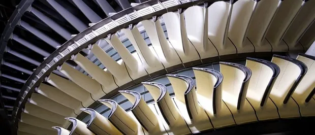
Thermomechanical fatigue (TMF) is cracking caused by temperature and strain cycling together: each start-up and shutdown strains a hot component because its layers and neighbours heat at different rates and cannot expand freely. Simulating it means computing the real metal temperature field, the cyclic stress and strain it produces in temperature-dependent material, and the damage per cycle, so the number of starts a casing, blade or manifold can take is known before the hardware exists.
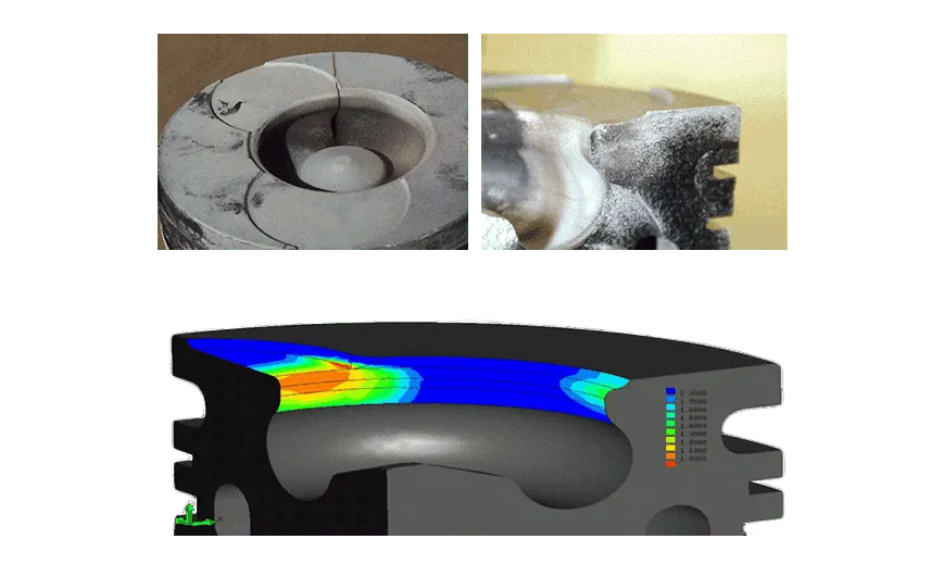
Gas and steam turbine casings and blades, exhaust manifolds and turbochargers, heat shields, boilers, pressure vessels and engine components all fail this way. The crack appears after months of service or in the qualification test, and the answer is a redesign, a slower start-up schedule, a derate or a shorter inspection interval. Each costs weight, efficiency, availability or warranty exposure. Our thermal stress simulation page describes the capability; this article explains the mechanism and how a permanent workflow is built around it.
Why do hot components crack when only the temperature changes?
A bar heated by ΔT wants to grow by ε = αΔT. If its ends are held, the mechanical strain that appears instead is −αΔT, and the stress is σ = −EαΔT. The product Eα is large for metals, so modest temperature differences give stresses comparable to yield strength, and hot alloys yield at lower stress than cold ones.
Real parts hold themselves back. In a thick wall the inner surface follows the gas quickly while the outer layers lag. For a wall that stays flat, the stress at each depth is approximately σ = −Eα (T − T̄) / (1 − ν), where T̄ is the mean wall temperature and ν is Poisson's ratio. The hot surface is compressed, the cold core is in tension, and the field balances itself. When the surface temperature steps at once, the surface stress approaches EαΔT/(1 − ν); a lower heat transfer coefficient lowers it.
- Hot gas sets the load. The gas or steam heats the wall through a heat transfer coefficient h, q = h (T gas − T wall). It changes with flow and position, so it comes from CFD, and it sets the metal temperature the stress model starts from.
- Conduction lag. Metal answers slowly. The Biot number Bi = hL/k says whether the wall stays uniform or builds a gradient; the Fourier number Fo = κt/L² says whether the ramp leaves time for heat to reach the outer layers.
- Through-wall gradient. While heating, the inner layers are hot and the outer layers are still cold. The stress follows the difference from the mean temperature, shown dashed.
- Restrained expansion. Each layer is held by its neighbours. The hot inner layer is pushed into compression, the cold outer layer pulled into tension. If the compression exceeds the hot yield strength the metal flows plastically.
- Flange and joint constraint. A massive flange heats slowly and holds the thin wall back. The differential expansion adds stress at the junction, on top of the gradient.
- Shutdown reverses the signs. Cooling the surface fast pulls it into tension, now on top of the plastic strain left from start-up. Oxidised, notched surfaces crack there, one cycle per start and stop.
Three things make this worse in practice. Different materials or thicknesses, such as a thin liner in a heavy casing or a flange on a thin wall, add differential expansion. Joints, bolts and fillets constrain and concentrate. And shutdown reverses the signs: the surface that yielded in compression when hot is pulled into tension as it cools, on a surface that has oxidised and may carry a notch. One cycle leaves a small plastic strain; thousands of cycles turn it into a crack.
How does heat transfer set the metal temperature? Biot and Fourier numbers
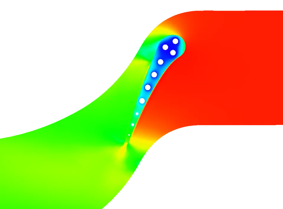
Stress follows temperature, so the temperature field comes first, and two dimensionless numbers say what to expect. The Biot number Bi = hL/k compares convection at the surface with conduction through a wall of thickness L and conductivity k. When Bi is small the metal stays nearly uniform and a lumped model is enough. When Bi is of order one or more, as for a thick wall in fast flow, the surface follows the gas and the interior lags. The Fourier number Fo = κt/L², with κ the thermal diffusivity, says how far heat has penetrated in time t. A ramp that is short compared with L²/κ leaves a gradient; a slower ramp lets the wall catch up. Ramp rate and wall thickness are the two levers you hold.
The coefficient h is not a handbook constant. It varies around a blade or along a casing with stagnation, cooling passages, film cooling and cavities, and it changes with load as the flow changes during start-up. We take it from CFD. Gas flow settles in seconds and metal in minutes, so the usual route is CFD at a few steady load points for h and a reference temperature, then transient conduction in the finite-element model with h interpolated in time. When the metal temperature feeds back on the flow, through radiation, strong property variation or deformation that changes clearances, two-way coupling is justified. See our pages on heat transfer for turbomachinery in CFD and in finite elements, thermal FSI and two-way thermal-structural FSI.
Validate the metal temperature before you trust a life number
What is thermomechanical fatigue, and how does it differ from isothermal fatigue?
In isothermal low-cycle fatigue, strain cycles at one fixed temperature. In thermomechanical fatigue, temperature and mechanical strain cycle together, and the phasing between them matters. Mechanical strain is total strain minus free thermal expansion, εmech = εtot − α(T − T0), and strain-controlled test methods such as ISO 12111:2011, Metallic materials, Fatigue testing, Strain-controlled thermomechanical fatigue testing method compensate for thermal strain so that this quantity is controlled against temperature.
In an in-phase (IP) cycle the part is in tension at peak temperature. In an out-of-phase (OP) cycle it is in compression when hot and in tension when cold. A surface heated while held back by cooler metal sees OP-like cycling; regions where centrifugal or pressure load adds tension at peak temperature move toward IP. Neither is always worse, and one component usually contains both.
- Mechanical strain. Total strain minus the free thermal expansion. It is the part the constraint imposes, and the quantity that TMF tests control against temperature.
- In-phase (IP). Strain and temperature rise and fall together, so the part is in tension when it is hottest. Tension at peak temperature tends to favour creep damage.
- Out-of-phase (OP). Strain falls as temperature rises: compression when hot, tension when cold, as in a hot surface held back by cooler material. Tension at low temperature tends to crack the oxide formed while hot.
- Hold time. A dwell at peak temperature lets stress relax by creep, which changes the loop and adds time-dependent damage on top of the cycle count.
- Isothermal reference. A test at one temperature cycles strain only. It is cheaper and easier, but it cannot show the effect of phasing between temperature and strain.
- Damage adds up. Fatigue, creep and oxidation each contribute in every cycle. Which one dominates depends on the alloy, the temperature range, the phasing and the hold.
Three damage processes act together. Fatigue damage grows with strain range. Creep damage grows with time at temperature under stress, so holds matter: during a hold, stress relaxes into inelastic strain. Oxidation embrittles the surface, and an oxide layer formed when hot can crack when stretched cold. Neu and Sehitoglu's two-part 1989 paper on thermomechanical fatigue, oxidation and creep (Part I, damage mechanisms; Part II, life prediction) treats these as separate damage mechanisms and builds a life prediction on them. Isothermal data at peak temperature cannot reveal the phasing effects. See our page on creep and creep-fatigue interaction.
How do you simulate thermomechanical fatigue life?
The chain runs from the operating cycle to boundary conditions, from CFD-derived h to a transient metal temperature, then to a stress-strain analysis through several cycles until the loop stabilises, and finally to a damage model. Temperature dependence runs through all of it: modulus, expansion, yield strength, cyclic hardening or softening and creep rate all change across the cycle. Once the metal is hot enough to relax during holds, rate-dependent (viscoplastic) behaviour matters. The analysis level follows the question.
| Level | Answers | Limit |
|---|---|---|
| Lumped or one-dimensional wall with the formulas above | Which ramp rates and thicknesses build a gradient worth analysing | No geometry, notches or joints |
| Transient thermal FE with CFD h over time | Metal temperature field and when the gradient peaks | Only as good as h; validate against thermocouples |
| Thermo-elastic FE with a notch correction | Fast ranking of strain range at hot spots | Misses relaxation and ratcheting where plasticity is large |
| Thermo-elasto-viscoplastic FE with temperature-dependent cyclic plasticity and creep | Strain range, mean stress and relaxation per cycle for the damage model | Needs calibrated material data; costly per run |
| Two-way coupled CFD and FE | Cases where metal temperature or deformation changes the flow | Highest cost; use once the feedback is shown to matter |
Design codes define the evidence a product must show. For high-temperature nuclear components the rules sit in ASME BPVC Section III, Division 5, High Temperature Reactors; boilers and pressure vessels carry their own fatigue rules in other codes, and which applies depends on your product and jurisdiction. We work to the code on your drawing and use simulation to generate its evidence, not to replace it. Blades also carry vibratory stress; see our article on flutter and forced response.
Where does AI/ML help with thermal stress and TMF, and where does it not?
AI/ML earns its place around the solver, and the solver stays the gate. Each use has a stated limit.
| Use | What it does | Limit |
|---|---|---|
| Surrogate over cycle and geometry parameters | Predicts peak metal temperature, gradient and strain range from ramp rate, hold time, wall thickness, fillet radius and an h scale, trained on planned transient runs | Valid inside the sampled range only; outside it the case returns to the solver |
| Start-up schedule screening | Ranks ramp rates and holds to find the shortest start that meets a life budget per start | The budget comes from the damage model and inherits its uncertainty |
| Calibrating h and material parameters | Fits h multipliers or hardening and creep parameters to thermocouple, strain-gauge and test data, with stated uncertainty | A parameter is identifiable only if the data excite it; a wrong model form is not rescued by a good fit |
| Reduced-order thermal models for monitoring | Replay recorded operating histories to estimate life consumed per start | Valid for the geometry and boundary types they were built from |
Material-model uncertainty is the limit no network removes. Cyclic plasticity, creep and oxidation data scatter between heats, coatings and surface conditions, and a damage model is calibrated over a finite range of temperature and phasing. We therefore report life as a range, show the inputs it is most sensitive to (h, material constants, hold time) and say which test would narrow it most. Surrogates inherit solver error, so we validate them on held-out transients. For the method, see our articles on surrogate models for CFD and FEA and validating AI surrogates, and our pages on surrogate modelling, hybrid physics and AI modelling and validation and benchmarking.
From one cracked component to a workflow you keep
A single study answers the component it was run for. The larger return comes when the load cycles, heat transfer data and material model become something your own engineers run for every new design, so the next casing, blade or manifold starts from a validated template, not a blank page. We build thermomechanical fatigue work this way.
- Physics model. CFD and FEA set up once, as templates: geometry clean-up, mesh, solver settings and post-processing that every later run reuses.
- Validation. Mesh and time-step studies, and comparison with tests or full-scale data, so the model's uncertainty is known before it is trusted.
- Automated runs. Scripted runs over the parameters and operating conditions that matter, on your hardware or in the cloud.
- AI surrogate. A machine-learning model trained on those runs answers in seconds and says how sure it is; low-confidence questions go back to the solver.
- Decision tool. Optimisation, trade-off charts or operating guidance, in a form your engineers and operators use every day.
- Field data. Test, trial and monitoring data flow back to recalibrate the model, so it improves with every project instead of being rebuilt.
- Templates for the duty cycles that matter (cold start, hot restart, load change, trip, shutdown), with the same temperature, stress and damage report for every part.
- A validation record comparing predicted metal temperatures and strains with your thermocouple, strain-gauge and rig data, with the deviation stated.
- Automated runs over ramp rate, hold time and heat transfer scatter, on your hardware or in the cloud.
- A trained surrogate that ranks schedules and design changes in seconds, with its range of validity written down and a route back to the solver outside it.
- A recalibration routine that refits heat transfer coefficients and material parameters when new test or field data arrive.
- Training and handover, so your engineers can extend the workflow themselves. See our training and software development services.
Questions engineers ask about thermomechanical fatigue simulation
What is the difference between thermal fatigue and thermomechanical fatigue?
Can elastic FEA predict TMF life?
Do we still need TMF tests?
Can simulation tell us how fast we can start the plant or engine?
Which software do you use?
If a hot component has cracked, or a start-up schedule is limited by life, send us the geometry, the materials with whatever temperature-dependent data you have, the duty cycle, any thermocouple or strain records, and photographs or locations of the cracks. You get a written diagnosis of which mechanism is at work, the analysis level the question needs and a plan for the workflow. Our thermal analysis and durability and fatigue work sits beside our consulting service, and the place to start is a conversation.