Welding distortion simulation for large fabrications, from weld sequence to pre-set
A girder leaves the welding bay bowed, and the question for the next unit is which seam to weld first, from which end, and how far to pre-set the parts. A moving-source weld model calibrates fast inherent-strain assembly models, and a surrogate ranks the weld sequences.
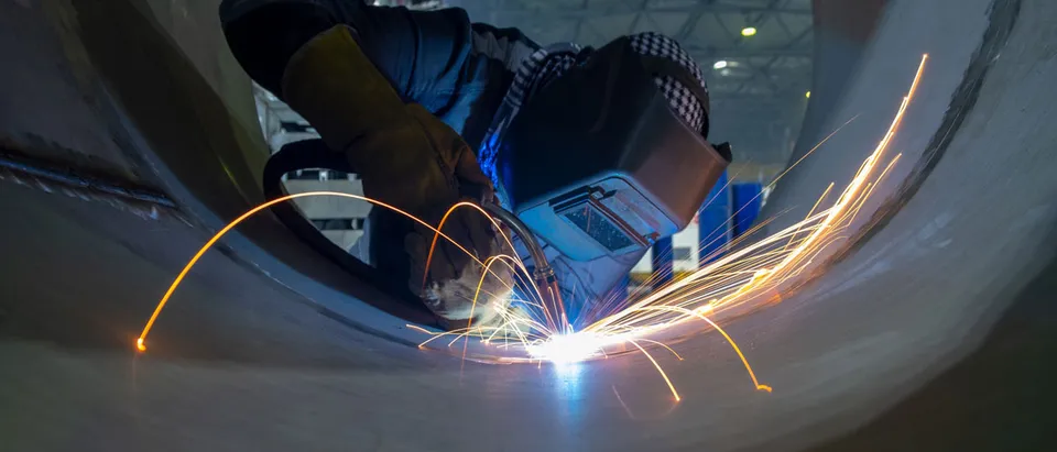
Welding distortion simulation predicts how far a fabricated structure shrinks, bows and twists as its arc welds cool, so weld sequence, fixtures and pre-set are chosen on a screen, not in the bay. We build it for large GMAW, GTAW and SAW structures: a calibrated moving-source weld model, fast assembly models and a surrogate that ranks weld sequences, on the solver you already use.
The first girder of a new design leaves the welding bay bowed, its end plates out of square with the next section. The straightening crew is booked and the jig needs a redesign. The question for the second unit has no answer on any drawing: which seam goes first, from which end, and how far should the parts be pre-set? Full-size trials answer it slowly, one assembly at a time.
What does welding distortion simulation have to predict?
The result that matters is the shape of the finished assembly at its interfaces: the gap at the next joint, the straightness of a girder, the flatness of a panel. Welding shrinks a structure across the joint and along it, and because contraction is not uniform through the thickness the parts also rotate, which is angular distortion.
The cause is a hot, narrow zone held by a cold, stiff surround. TWI notes that in CMn steel the molten weld metal loses about 3% of its volume on solidification and the solidified weld metal and heat-affected zone a further 7% as they cool to room temperature, and that stress above yield leaves permanent plastic deformation. What remains is a band of plastic strain around each seam, and the rest of the structure responds to it elastically.
Acceptance is a tolerance on the drawing. ISO 13920:2023 gives general tolerances for linear and angular dimensions and for shape and position of welded structures in four classes, and the tolerances that apply are those stated on the drawing. The model gives a predicted deviation at each interface to set beside them.
Why is arc weld distortion so hard to calculate?
Three problems share one model. The first is the moving source. Arc power into the work is Q = ηVI, with efficiency η, voltage V and current I, and heat input per unit length is Q/v at travel speed v. It lands over a volume, not a point: the standard description is the double-ellipsoid source of Goldak, Chakravarti and Bibby, in a frame moving with the arc, where x is across the weld, y is depth into the plate and ξ is distance ahead of the arc:
qf = 6√3 ff Q / (π√π a b cf) · exp[−3x²/a² − 3y²/b² − 3ξ²/cf²] for ξ ≥ 0, and the same with fr and cr behind the arc, with ff + fr = 2. The lengths a, b, cf and cr are not material properties. They are calibrated until the computed fusion line matches a macrograph of the real weld, so each process, joint and parameter set needs its own.
The second is the filler. The model starts with the groove elements inactive and activates them as the source reaches them. The third is material behaviour that depends on temperature and, in steels, on phase: yield strength falls on heating and recovers on cooling, and the transformation of austenite changes volume and strength, which sets the residual stress that remains. In a V joint the second run rotates the plates about the first deposit, as TWI describes.
- Moving heat source. The arc delivers a power Q = ηVI that travels along the joint at speed v. The model spreads it over a double-ellipsoid volume, shorter ahead of the arc than behind it. The lengths of that volume are calibrated until the computed fusion line matches a macrograph of the real weld.
- Filler by element activation. The groove is meshed from the start with its elements switched off. As the source reaches each one it is activated, so weld metal joins the model behind the arc as the real filler does, and the elements ahead of it stay out of the calculation.
- Trailing temperature field. Heat flows into the plate and leaves a hot band that is long behind the arc and steep ahead of it. Every point passes through a thermal cycle of heating, peak temperature and cooling, and that cycle sets how much plastic strain stays behind.
- Thermal, metallurgical, mechanical. The temperature history drives the phase transformations in the steel, which change volume and strength, and both feed the stress calculation. The chain runs once per pass, or once per group of passes that the validation record shows can be lumped.
- Shrinkage and angular distortion. The weld metal and the metal beside it contract on cooling against the cold plate around them. The contraction is not uniform through the thickness, so the plates rotate toward the weld side, which is angular distortion, and the joint also shortens across and along the seam.
- Strain left in the weld zone. What stays after cooling is plastic strain in a band around the seam. This is the strain that a fast assembly model carries in place of the moving source, which is why it has to be calibrated against the detailed joint model or a measurement.
How are large welded structures usually handled, and where does that break?
Mostly by experience. TWI gives a rule of thumb for shrinkage allowances and calls the amount almost impossible to predict accurately. TWI on pre-setting and restraint says the same of pre-setting: a number of trial welds will be required, so it suits simple assemblies. Restraint is more widely practised, but it adds residual stress that can crack susceptible materials, and the part still moves a little when it leaves the fixture.
Calculation has its limit too. A moving-source thermal elastic-plastic analysis of every pass is physically complete, but Murakami and co-authors in ISIJ International note that it is not always realistic for production sites and design departments, given the calculation time on large structures such as ships and construction machinery. The shortcut is the inherent strain method and its thermal shrinkage variant: apply the strain left by each weld to a model of the whole assembly, at extremely short calculation time. In the thermal shrinkage form that strain is ε = −αΔT inside a zone around the weld. The catch is the input: the same paper states that a shrinkage strain is needed for each welding condition and each joint, and that setting it is arbitrary. An uncalibrated shortcut is a guess that runs fast. Our article on metal additive manufacturing distortion covers the same idea for layered builds.
Sequence is the third limit. TWI recommends welding towards the free end of the joint, with short back-step or skip runs on long welds. An assembly of r seams, each weldable in either direction, has r! × 2r orders. Eight seams give 10,321,920, the example Wu and Kim use in their review of FEM-based distortion mitigation, where a genetic algorithm is the most common search and thousands of thermo-elastic-plastic cases make computation time the obstacle.
| Question | Model | What it hands on | Decision it supports |
|---|---|---|---|
| How does this joint shrink and rotate? | Moving-source thermal-metallurgical-mechanical model of a representative joint | Calibrated heat source and the strain each seam leaves | Which seams need their own calibration |
| What shape does the whole assembly take? | Inherent-strain or thermal-shrinkage model of the full assembly | Distortion at each interface, seam by seam | Whether the drawing tolerance is met, and which seam drives a miss |
| Which weld sequence and direction? | Assembly model over a designed set of orders, ranked by a surrogate | Ranked orders with a stated range | The order to try first |
| How should it be clamped and set? | Assembly model with clamp contact and release steps | Pre-set shape, clamp layout, release order, springback | Fixture changes before the jig is cut |
| What stress is left in a critical joint? | Full moving-source model of that joint, refined locally | Residual stress at weld toe and root | Input to your fatigue or fracture assessment |
How do you build a weld model your engineers can trust?
We split the problem the way the table does. On a representative joint we build the full model in LS-DYNA, Ansys, Abaqus or your existing thermal-structural solver: source, element activation, temperature- and phase-dependent properties, and the passes as you weld them, lumped into one step only where the validation record shows it holds. The thermal result is verified first, fusion line against the macrograph and heat balance against ηVI/v, then mesh and time-step convergence, then the measured distortion of a test piece. The strain each seam leaves goes into a library that the assembly model reads. Our arc welding and welding simulation pages set the wider context.
Uncertainty is stated, not hidden. Arc efficiency, heat-source lengths, high-temperature material data, fit-up and restraint all move the answer, so we sweep them and report distortion as a range with its assumptions. Residual stress from a critical joint then passes to your fatigue life assessment with its range.
- Same seams, different order. Each seam leaves its own shrinkage and is welded onto a structure that earlier seams have already stiffened and pulled. Order and direction therefore change the final shape, not only its size, and the model compares orders on the interface distortion your drawing tolerances care about.
- Seam library and assembly model. The strain each seam type leaves comes from a calibrated joint model and is stored once. The assembly model applies it seam by seam, in the chosen order, to the whole structure with its clamps, in a calculation fast enough to run for many orders.
- Surrogate over sequences. A surrogate trained on a designed set of assembly runs predicts distortion at the interface points for any order and direction inside its stated range, so a search over millions of orders runs on it and not on the solver.
- Full-model check and recalibration. The best few orders go back to the full model for confirmation. When a first article is measured, the difference feeds back into the seam library, and a request outside the surrogate's range goes to the full model instead.
- Pre-set. Where distortion is consistent, parts can be set the opposite way so that the shrinkage of the welds pulls them into the correct shape. The model proposes the pre-set shape and a trial assembly confirms it.
- Clamp release. Clamps hold the shape during welding, but the stress they lock in relaxes when the part leaves the fixture and it moves a little. The assembly model includes the release step, so the released shape is predicted and not discovered at unclamping.
Where does AI help weld sequence optimisation, and where does it not?
- Sequence ranking. A designed set of orders runs through the assembly model, and a surrogate trained on those runs predicts interface distortion for any order. The search over millions of orders runs on the surrogate, and only the best few return to the full model.
- Calibration. Fitting heat-source lengths and shrinkage inputs to the measured fusion line and distortion is an inverse problem that automated fitting makes repeatable.
- Run triage. Checks reject non-converged or energy-unbalanced runs before they reach the training set.
It does not replace the physics. A surrogate predicts only inside the joint types, grades and process window it was trained on, inherits the errors of the model behind it, and cannot tell that a new consumable or joint preparation changed the answer, so each carries a stated range. Wu and Kim recommend inherent-strain models as the fast inner model for AI-driven optimisation, since thousands of full runs cost too much. See AI surrogate models you can validate.
A distortion prediction is not a qualification
From one distorted assembly to a distortion-control workflow you keep
The return comes when the next assembly, sequence or fixture revision runs through the same chain without a new model or new full-size trials.
- Physics model. CFD and FEA set up once, as templates: geometry clean-up, mesh, solver settings and post-processing that every later run reuses.
- Validation. Mesh and time-step studies, and comparison with tests or full-scale data, so the model's uncertainty is known before it is trusted.
- Automated runs. Scripted runs over the parameters and operating conditions that matter, on your hardware or in the cloud.
- AI surrogate. A machine-learning model trained on those runs answers in seconds and says how sure it is; low-confidence questions go back to the solver.
- Decision tool. Optimisation, trade-off charts or operating guidance, in a form your engineers and operators use every day.
- Field data. Test, trial and monitoring data flow back to recalibrate the model, so it improves with every project instead of being rebuilt.
- A seam library of calibrated heat-source and strain inputs per joint type, process, consumable and material, each with the measurement it was checked against and its pass-lumping rule.
- A weld-plan template in your existing solver that reads your weld list and takes sequence, direction and clamp steps as input, so a new sequence is a line in a file.
- A sequence study runner that executes the designed orders on your hardware, rejects failed runs and collects distortion at the interface points.
- A surrogate with a stated range and a gate: anything outside its joint types, grades and process window goes to the full model.
- A validation record against your first article, with tolerances written before the run and every model update logged.
- Handover and training, so your team adds seams itself. See our training and software development services.
Questions engineers ask about welding distortion simulation
What is the inherent strain method in welding simulation?
Does the welding sequence change distortion?
How accurate is welding distortion simulation?
Can simulation replace welding procedure qualification or inspection?
If a weld sequence, fixture or pre-set is waiting on a distortion answer, send us the weld list (seams, process, passes, consumable, material), the drawing with its interface tolerances, your current sequence and fixture arrangement, and measured deviations of one finished assembly if you have them. We reply with how we would split the joint model from the assembly model, which seams to calibrate first, and what the validation record should hold. Start with a conversation.