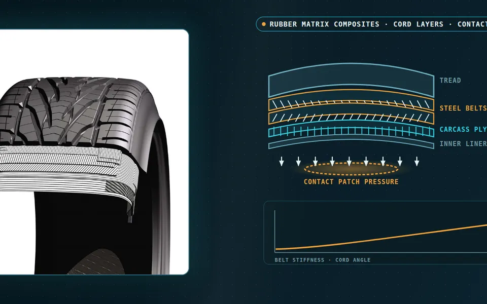
Hot forging simulation: die life, preform design and defects before the first try-out
Dies wear out, ribs do not fill and laps appear in the same place every shift. How coupled thermo-mechanical simulation, a calibrated flow-stress card and a wear model predict fill, load, defects and die life, and where AI/ML helps and where it does not.
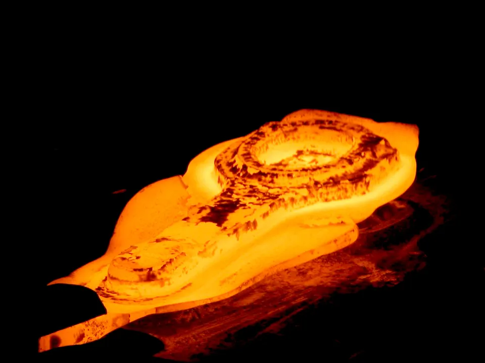
Hot forging simulation predicts, before a die is cut, whether the heated billet fills the cavity, how much press load it takes, where laps and underfill form and how long the die will last. It does this by solving temperature, large-strain flow and contact between workpiece and die together, with a flow-stress law and a friction model calibrated on your own alloy and lubricant.
The questions arrive as shop-floor symptoms: the die is gone before the order is finished, one rib fills only when the billet is hot enough, the same lap shows up at the same fillet. Each costs die replacement, scrap, reheating energy or press time, and is decided before the first try-out by preform shape, billet temperature, flash design, die steel and shrink-fit layout. Our hot forging simulation page and the metal forming simulation hub describe the capability; this article explains the mechanisms and the workflow around them. Open-die work has its own page: open-die forging.
How does hot forging simulation work?
Three things are solved together. The workpiece deforms plastically at large strain, so the mesh is rebuilt as it distorts. Heat moves at the same time: the billet cools against the die, plastic work heats it, and the die skin takes up heat on every blow. And contact carries pressure and friction. You get the filling sequence, load against stroke, and the pressure and sliding the die survives.
Two inputs decide whether the answer can be trusted. The first is the flow stress, the resistance of the hot metal as a function of strain ε, strain rate ε̇ and temperature T. Hansel-Spittel-type laws write it as a product of power and exponential terms in these three variables, with up to nine parameters (see the fit described by Chen and co-authors). The Zener-Hollomon parameter Z = ε̇ exp(Q/RT), from Zener and Hollomon's 1944 paper on the effect of strain rate upon the plastic flow of steel, combines rate and temperature into one measure of the deformation state, with Q the apparent activation energy and R the gas constant. The calibration problem is practical: the parameters are fitted to hot compression tests over a grid of temperatures and rates, nine parameters from limited data are not uniquely determined, and a good fit says little about a billet chilling at the die surface. We fit by inverse optimisation, report the uncertainty and check the card on a forging.
The second input is friction. The usual model is shear friction, τ = m k, where k = σ̄/√3 is the shear flow stress and m runs from 0 (no friction) to 1 (sticking). The factor m depends on lubricant, graphite application, die temperature and speed. A ring-compression test measures it: how far the inner diameter of an upset ring shrinks or grows depends on friction. Contact with the cooler die also chills the workpiece skin, which raises its flow stress where the metal must flow into thin ribs.
Validate force, fill and workpiece temperature before you predict die wear
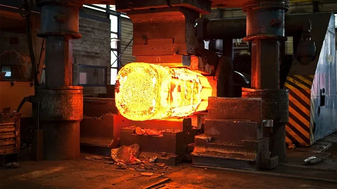
Why do forging dies fail? Wear, heat checking and overload
Dies are retired by several mechanisms acting on different parts of the same cavity. Ficak, Łukaszek-Sołek and Hawryluk's 2024 review of the durability of tools in hot closed-die forging names the main ones: abrasive wear, plastic deformation of the die surface, thermal and thermo-mechanical fatigue and fatigue cracking, with adhesive wear and oxidation alongside. No single mechanism applies to the whole cavity, so a die-life model has to say where each one acts.
- Abrasive wear. Hot metal slides along the cavity walls and rib flanks under high contact pressure. In the Archard picture, wear depth grows with contact pressure and sliding distance and falls with surface hardness, so the walls that carry the metal flow wear first.
- Heat checking. Each stroke heats the die skin and spray or contact cools it. The surface cycles in temperature while the core stays cooler, so a network of fine cracks forms: thermal fatigue of the die.
- Fatigue crack from a fillet. A small radius at the bottom of a deep rib concentrates stress in every blow. A crack starts there and grows into the insert until it breaks or the die is retired.
- Shrink-fit ring. The ring is fitted tight around the insert, so the insert sits in compression and the ring in tension. The pre-stress keeps tension out of the insert during the blow, and the fit changes with temperature.
- Load and plastic deformation. The land and bridge carry the full press load at working temperature. When the stress exceeds the hot yield strength of the die steel, the surface sinks and the forging goes out of tolerance.
- Spray and chilling. Lubricant sets friction between die and workpiece and cools the die between strokes. It also chills the workpiece skin, so friction and temperature are model inputs, not constants.
Abrasive wear is the part simulation predicts best. In the form usually attributed to Archard's 1953 paper on the contact and rubbing of flat surfaces, wear volume is V = K F s / H, with normal force F, sliding distance s, hardness H and a wear coefficient K; per unit area the depth is h = K p s / H. The finite-element result supplies p and s at every point of the die surface for each blow, and the die steel softens as it heats. The review notes that Archard-based models describe abrasive wear well and the other mechanisms much less so.
Heat checking is thermal fatigue of the die. Every blow heats the skin and every spray cools it, so the surface cycles in temperature while the core does not. The constrained-expansion physics, σ ≈ EαΔT/(1 − ν) for a sudden surface step, is the one in our article on thermomechanical fatigue, and so is the caution: life depends on a calibrated thermal-fatigue criterion for your die steel, not on stress alone. Fatigue cracks also start at small fillets (see our durability and fatigue life work), and plastic deformation sinks lands and bridges when stress at working temperature exceeds the hot yield strength.
Shrink-fit inserts change the stress state: the ring holds the insert in compression so that the blow does not put it in tension. A die stress analysis therefore includes the fit interference, the temperatures of insert and ring, and the blow load.
| Mechanism | Main drivers | What the simulation gives | What it cannot tell you alone |
|---|---|---|---|
| Abrasive wear | Pressure, sliding, die temperature, hardness, lubricant | Pressure and sliding per blow; wear depth map | The coefficient K for a new die steel or lubricant |
| Heat checking | Surface temperature swing per blow, contact time, cooling | Die surface temperature history and stress range | Life, without a criterion calibrated for the die steel |
| Fillet fatigue crack | Local stress at the notch, shrink-fit pre-stress, blow load | Die stress with fit and blow load; the radius that lowers the peak | Crack growth without hot material data |
| Plastic deformation | Press load, contact area, land temperature | Stress against hot yield strength at lands and punches | Hot strength after service tempering |
How do you design a preform and avoid laps, folds and underfill?
A preform is the intermediate shape that puts the volume where the finishing die needs it. Its job is to fill the cavity at low load with little flash. Underfill happens where the metal never reaches a tall rib or far corner, often because it takes the easier path out through the flash. A lap or fold forms when a surface flows over itself and is pressed shut, leaving an oxidised seam in the part. Both follow from the flow path, which the preform sets.
- Heated billet. Volume and temperature at the start. The billet loses heat in handling and on contact with the die, so the temperature at the blow is not the furnace temperature.
- Preform. An intermediate shape that puts the volume where the finishing die needs it. Lengths, radii and the split of volume are the design variables.
- Underfill. A tall thin rib or a far corner that the metal does not reach. The metal chooses the easier path through the flash first.
- Lap or fold. A surface that flows over itself and is pressed shut, leaving an oxidised seam inside the part. It depends on the preform shape and the flow path, not only on the final shape.
- Force against stroke. Load rises slowly while metal flows, then steeply as the flash thins and the cavity closes. The peak must stay below press capacity and the die stress limit.
- Flash and trim. Flash is the throttle that builds pressure to fill the cavity. It costs material and trimming load, so a good preform keeps it small.
- Flow lines and microstructure. The finished part keeps the history of strain and temperature at each point. Local grain size and flow-line direction follow from it.
- Surrogate over preform parameters. Trained on planned simulation runs, it ranks preform candidates for fill, load and lap risk in seconds. The solver confirms the best ones, and cases outside the sampled range go back to it.
Simulation makes the flow path visible: the filling sequence, the surface points that fold, flow lines and the force curve. Flash is the throttle that builds the pressure needed for fill, so a long thin land raises load while a thick one wastes material and trimming force. A preform study varies lengths, radii, the split of volume, billet position and temperature, and scores each candidate on fill, peak load against press capacity, flash mass and a lap flag. Temperature is a trade-off: a cooler billet saves reheating energy but raises flow stress, so load and die stress rise.
Can you predict grain size and properties in a forging?
Yes, as a map, with calibration. The strain, rate and temperature history at each point decides whether the metal recrystallises during deformation, between blows and in the cool-down, and how far the grains grow. The simulation supplies the local history; a microstructure model turns it into recrystallised fraction and grain size. The model must be calibrated for your alloy and checked against sections cut from forgings, with grain size measured by a standard method such as ISO 643:2024, Steels, Micrographic determination of the apparent grain size.
Where does AI/ML help forging simulation, and where does it not?
AI/ML earns its place around the solver, which stays the gate. Each use has a stated limit.
| Use | What it does | Limit |
|---|---|---|
| Surrogate over preform parameters | Predicts fill, peak load, flash mass and wear index from preform lengths, radii, volume split and temperature | Valid inside the sampled range; outside it the solver runs |
| Calibrating flow stress and friction | Fits the material card and friction factor to compression and ring tests, with uncertainty | A parameter is identified only if the test excites it |
| Wear-model calibration | Fits the wear coefficient to measured die profiles; Wilkus and co-authors (2015) identified Archard-model parameters from worn dies this way | Holds for that die steel, lubricant and temperature range only |
| Anomaly gate on press-force signals | Compares each blow's force signal with the predicted band and flags departures | It flags, it does not diagnose; needs a stable recorded baseline |
Where it does not help: predicting wear for a new die steel, coating or lubricant with no wear data. The coefficient K is empirical, and a network cannot supply it. Published neural-network work, as the review above describes, only estimates which mechanism dominates from existing records. We plan the shortest wear trial that gives the calibration. See our articles on surrogate models for CFD and FEA and validating AI surrogates, and our pages on surrogate modelling and validation and benchmarking.
From one die problem to a forging workflow you keep
A single study answers the die it was run for. The larger return comes when material cards, friction data and wear records become something your engineers use for every new part, so the next die starts from a validated template. We build hot forging work this way.
- Physics model. CFD and FEA set up once, as templates: geometry clean-up, mesh, solver settings and post-processing that every later run reuses.
- Validation. Mesh and time-step studies, and comparison with tests or full-scale data, so the model's uncertainty is known before it is trusted.
- Automated runs. Scripted runs over the parameters and operating conditions that matter, on your hardware or in the cloud.
- AI surrogate. A machine-learning model trained on those runs answers in seconds and says how sure it is; low-confidence questions go back to the solver.
- Decision tool. Optimisation, trade-off charts or operating guidance, in a form your engineers and operators use every day.
- Field data. Test, trial and monitoring data flow back to recalibrate the model, so it improves with every project instead of being rebuilt.
- A validated material and friction library: flow-stress cards for your alloys and lubricants, each tied to the tests it came from, with uncertainty stated.
- A templated forging model with automated preform studies, reporting fill, peak load, flash mass and laps in the same format every time.
- A wear-calibration record: predicted wear depth set against your scanned or measured worn dies, with coefficients and range of use written down.
- A surrogate with a stated range for fill, load and wear against preform parameters, and a route back to the solver outside it.
- A press-force gate that flags blows departing from the predicted force band.
- Training and handover, so your die designers can extend the workflow themselves. See our training and software development services.
Questions engineers ask about hot forging simulation
How accurate is die wear prediction?
Which flow stress model should we use for hot forging?
Can simulation predict heat checking?
Do we still need a try-out forging?
Which software do you use?
If a die is wearing out early, a rib will not fill or a lap keeps coming back, send us one part number with its die drawing, the alloy and any compression data, billet temperature and lubricant practice, the press-force record, die-life records with the failure mode, and a scan of a worn die if you have one. You get a written diagnosis of which mechanism limits the die, the model level it needs, the test that would narrow the uncertainty most, and a plan for the workflow. Our metal forming and durability work sits beside our consulting service, and the place to start is a conversation.