Heart valve simulation for leaflet fatigue, paravalvular leak and blood flow
The valve frame is close to design freeze, the wear tester takes only a few builds and the leak question from the last bench round is still open. Simulating leaflets, frame, root and flow together ranks the candidates on a documented model before the builds are committed.
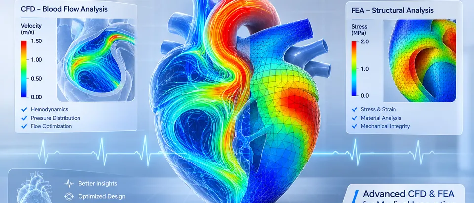
Heart valve simulation predicts how a transcatheter or surgical valve behaves before it is built: how its leaflets strain and wear, how its frame seats in a calcified, non-circular root, where blood leaks past it and how long blood lingers or shears around it. We build that model around your existing solver, so a leaflet profile, frame cell or skirt is compared on a documented model before the next build and the next wear-test slot.
Design freeze is close. Three leaflet profiles and two frame cell patterns are on the table, only a few builds fit the accelerated wear tester, and the last bench round left a paravalvular leak question open. The design-assurance lead will ask why these builds. A model can answer if it carries leaflets, frame and root together and you can say what its output is good for.
What does heart valve simulation have to answer?
Three couplings make a valve hard. The leaflets are thin, anisotropic tissue or polymer that strain heavily every cycle: for a thin spherical membrane of radius R and thickness t, closing pressure p gives a stress of σ = pR/(2t), so thickness and curvature set the load before any material law is chosen. The frame is pressed into a root that is rarely round and is stiffened by calcium. Blood passes a narrow orifice into sinuses behind leaflets that move with the flow.
- Frame in a calcified root. The frame is held by the root it is deployed into. Calcium stiffens the native cusps and the annulus, so the contact the frame meets is set by anatomy, and the shape the frame ends up in is the shape the leaflets have to work in.
- Leaflets, two poses. Pressure pushes the leaflets open against the frame, then closes them into a cup where the free edges meet. The model carries both poses and the contact between leaflets at closure, because the strain history of every cycle decides where fatigue damage concentrates.
- Jet and shear layer. Blood accelerates through the open orifice and a shear layer forms at the edge of the jet. The shear stress a blood particle meets, added up over the time it spends there, is the exposure a flow model reports.
- Sinus vortex and washout. Behind the open leaflets each sinus holds a slow vortex. The dots are particles circulating, and some leave with each cycle. How many cycles a particle needs to leave can be measured, and it depends on valve and root shape.
- Closure load and strain. Once closed, the leaflets carry the pressure above them as membrane tension of order pR/2 per unit width. Strain concentrates at the commissures and along the attachment lines, and these hot spots are what a fatigue ranking compares.
- Calcium and the leak path. Where calcium holds the frame off the wall, a channel opens between frame and root. In diastole blood returns through it, outside the skirt. Its size and place change with frame height, orientation and expansion, which is why one root is not enough.
How do you simulate leaflet stress and fatigue?
In the finite element study by Martin and Sun, bovine pericardium was a Fung-type anisotropic hyperelastic material and a phenomenological damage law grew damage each cycle from the peak equivalent strain. Peak damage fell on the aortic side of the leaflets, and heterogeneous leaflet properties, poor coaptation and little stent-tip deflection may accelerate fatigue.
The same paper marks the limit of any durability simulation. The authors state that the fatigue parameters “were not rigorously determined due to limited experimental data”, so the damage at a given cycle state may not be accurate. The model gives a comparison between cases and a reason for it. We use it that way, to rank leaflet and frame candidates and show where damage starts, while the accelerated wear test produces the evidence. See our durability and fatigue work.
Crimping matters too. Bressloff (2022) crimped a full self-expanding model of frame, skirt and leaflets to 6 mm. Peak stress sat near the suture lines joining leaflets and skirt and along axial folds, and it depended on leaflet thickness and material model. The crimp needed a finely resolved skirt, meshed at 0.05 mm in the final runs, and the model used radial displacement where real crimping pulls the valve axially through a funnel.
How does a valve seat in a calcified, non-circular root?
A frame deployed into a calcified root takes its shape from contact with the root, not only from its nominal diameter. Mao and colleagues rebuilt one root from CT, calcified native leaflets included, simulated deployment of a self-expanding valve by finite element analysis, then ran CFD of diastolic flow on the deployed geometry to read the leak. Skirt orientation changed the leak by as much as 40%, deployment height changed the leaking volume by up to 70%, and a wrong stent thickness could underestimate it by up to 10 ml per beat. The model was built and validated with data from one patient, and the authors ask for a larger cohort.
That is why one root is never enough, and why a one-off study does not survive the next design revision. A design tool needs a set of roots, from your CT geometries or generated by parameters, with calcium, frame height and frame rotation as inputs to sweep. The result is a spread of leak volumes across anatomy, not one number.
- Non-circular annulus. The native annulus is often closer to an ellipse than a circle. A circular frame deployed into it presses on part of the wall and leaves crescent gaps elsewhere. The model starts from the range of root shapes you design for.
- Calcified nodules. Calcified cusps and nodules are stiff and uneven. They resist expansion where they sit, so contact concentrates on them and the frame can be held off the wall beside them.
- Frame, skirt and leaflets. The frame leaves the delivery system crimped and expands until the radial force it applies balances what the root resists. The pulsing rings show the expansion. The final shape comes from contact, not from the nominal diameter.
- Contact points. Contact is highest where the frame meets calcium and the stiffer parts of the wall. These points anchor the frame, and the strain they put into its cells is an output the model reports.
- Gap channels. The skirt seals only where it is pressed against the wall. Where a gap remains, diastolic flow returns through it, and the pulses mark each channel. The size of the gap, not the average fit, sets the leak.
- Orientation and height. Turning the frame moves its commissures and cells against the calcium and the gaps, and sliding it up or down changes how much skirt sits at the annulus. The leak changes with both, so the model sweeps them.
What do CFD and FSI add to a valve model?
Closure, washout and shear need the fluid in the model. Luraghi and colleagues reproduced pulse duplicator tests of a polymeric valve with a structural model and an FSI model. At maximum opening the orifice area differed from the measurement by about 5% for FSI and about 46% for the structural model in one of two flow conditions, and they note that wall shear stress and velocity still need validating. Where flow drives leaflet motion, the stress you report depends on solving it. See our medical FSI page.
Washout is measured before it is simulated. Hatoum and colleagues tracked particles seeded in the sinus of two 3D-printed patient roots in a pulsatile left-heart simulator. In one root, 37.82% of the particles left the sinus in the first cycle with one valve design and 18.17% remained after ten cycles, while a second design cleared 75% in the first cycle. A CFD washout result is credible to the degree it reproduces a comparator like this. For shear, the stress along each particle path, added up over the time spent under it, is the quantity, so we report its distribution, not a snapshot peak.
| Question | What the model carries | What it reports | Decision it supports |
|---|---|---|---|
| Crimp and leaflet folding | Frame, skirt, leaflets, contact | Leaflet stress at folds, frame strain | Which designs to build and crimp-test |
| Seating in a calcified root | Deployment into a root set with calcium | Contact map, frame shape, gaps | Frame and skirt design, sizing range |
| Paravalvular leak | Deployed geometry and diastolic CFD | Leak paths and volume across roots | Skirt shape, positioning window |
| Leaflet fatigue ranking | Leaflet cycle with a calibrated damage law | Strain and damage distribution, ranking | Which candidates go to the wear tester |
| Opening and closure | FSI with leaflet contact | Orifice area, closure motion, leaflet stress | Leaflet profile and thickness |
| Washout and shear exposure | CFD, rigid-wall or FSI, with particle tracking | Residence time, shear exposure over paths | Sinus and frame geometry |
How credible is a heart valve model, and for which decision?
Credibility depends on what the model is used for. The FDA guidance Assessing the Credibility of Computational Modeling and Simulation in Medical Device Submissions (November 2023) draws on ASME V&V 40-2018, Assessing Credibility of Computational Modeling through Verification and Validation: Application to Medical Devices. You state the question of interest and the context of use, then rate model risk from model influence, the model’s contribution relative to other evidence such as bench tests, and decision consequence, the significance of an adverse outcome if the decision is wrong. The credibility needed follows the model risk.
Our example context of use: finite element analysis ranks three leaflet profiles by strain at closure so that two are built for the wear tester. Model influence is moderate because the wear test still decides. If the same model supported a durability statement in a submission, influence and the validation evidence needed would rise. How far virtual evidence is accepted for a context of use is agreed with the regulator, and the guidance points to the Q-Submission programme for feedback on a credibility assessment plan.
ISO 5840 sets the wider frame. The scope of ISO 5840-1:2021 (Cardiovascular implants — Cardiac valve prostheses — Part 1: General requirements), as listed by the Swedish standards body, outlines verification and validation through risk management, with tests chosen from the risk assessment, including preclinical in vivo and clinical evaluation. Parts 2 and 3 cover surgical and transcatheter valves.
The model work follows one order. Verification: mesh and time-step convergence, contact and energy checks. Validation: against pulse duplicator, deployment bench and particle-tracking data at conditions you set, with tolerances fixed before the run. Uncertainty: tissue batch, root shape, calcium, placement, friction and fatigue parameters, swept so each result is a range.
A valve model is not a durability test
Where does AI help heart valve design, and where does it not?
- Screening. A surrogate trained on runs over leaflet, frame, skirt and root parameters returns leaflet strain, crimp strain and contact gaps for any design inside its range, so the full model runs on the finalists. See surrogate models for CFD and FEA.
- Calibration. Material and fatigue parameters are fitted to your test data by an inverse method that returns a range for the uncertainty record.
- Run gating. A script flags runs that diverge or lose contact, as three of the six leaflet cases in the Martin and Sun study did, so a failed run is never read as a result.
It does not replace material data or the bench test, and a surrogate cannot predict outside its range. The FDA guidance applies to first-principles models, not standalone machine-learning or statistical models, and for a data-driven model it points to a Q-Submission. So we keep the surrogate downstream: it chooses where to run the physics model, and the physics model with its validation record carries the evidence. See AI surrogate models you can sign off.
From one valve study to a design workflow you keep
The return comes when your engineers can put the next leaflet profile, frame cell or skirt through the same chain without rebuilding anything.
- Physics model. CFD and FEA set up once, as templates: geometry clean-up, mesh, solver settings and post-processing that every later run reuses.
- Validation. Mesh and time-step studies, and comparison with tests or full-scale data, so the model's uncertainty is known before it is trusted.
- Automated runs. Scripted runs over the parameters and operating conditions that matter, on your hardware or in the cloud.
- AI surrogate. A machine-learning model trained on those runs answers in seconds and says how sure it is; low-confidence questions go back to the solver.
- Decision tool. Optimisation, trade-off charts or operating guidance, in a form your engineers and operators use every day.
- Field data. Test, trial and monitoring data flow back to recalibrate the model, so it improves with every project instead of being rebuilt.
- A valve model template in your existing solver: frame, skirt, leaflets, crimp, deployment and contacts.
- A root set from your CT geometries or parameters, with calcium, frame height and rotation as inputs.
- A calibration script from your biaxial and fatigue test files to material and damage parameters, with the fit and its range on record.
- Flow templates for leak, closure, washout and shear exposure.
- A validation record against your pulse duplicator, deployment bench and particle-tracking data, with tolerances set before the run.
- A surrogate with a stated range and a gate to the full model outside it.
- Handover and training, so your team runs and extends it. See our training and software development services, and the medical and biomedical devices hub.
Questions engineers ask about heart valve simulation
What is heart valve simulation used for?
Can finite element analysis predict heart valve durability?
How is paravalvular leak simulated?
Does a heart valve model need FSI?
Can simulation replace accelerated wear testing?
If a valve frame or leaflet freeze is waiting on a build decision, send us the leaflet and frame drawings with materials, the root shapes you design for, any CT geometries, the bench results you hold and the decision the model should inform. We reply with how we would build the model, the outputs it would report and what the validation record should contain. Start with a conversation, or read the cardiovascular implants capability page.