Stent finite element analysis for crimping, deployment and pulsatile fatigue
A strut layout that looks sound can fracture at one crown in the pulsatile rig, after the samples are built and the slot is spent. Simulating crimp, release and pulse on your own solver finds the governing size and crown first.
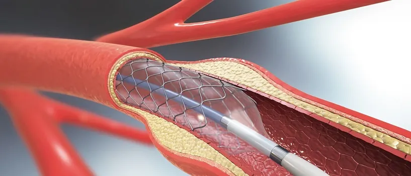
Stent finite element analysis predicts how a stent or stent-graft deforms when it is crimped, released into a vessel and loaded by every heartbeat, and where the strain at the struts is highest. We build it around your existing solver, so a strut layout, heat treatment or oversizing range is compared on mean and alternating strain, radial force and a fatigue margin before samples are cut and a pulsatile rig slot is booked.
The design freeze for the next size matrix is close, and a longer lesion has forced a change to the strut layout. The durability rig reports fracture or survival only at the end. Which size governs, which crown breaks first, and what does the change cost in radial force? A wrong guess becomes a failed run and a moved submission date. FDA's guidance on non-clinical engineering tests for intravascular stents recommends a fatigue analysis and says accelerated durability testing validates it: the analysis is the plan, the rig the check.
What does stent finite element analysis have to capture?
One model, three load steps: crimping packs the stent into its delivery system, release lets it expand until the vessel wall stops it, and pulsatile loading cycles the vessel diameter with every heartbeat. ASTM F2514-21, the guide to finite element analysis of metallic vascular stents, lists the same sequence and says such analysis is frequently used to find the worst-case size for fatigue testing and to tell designs apart.
A balloon-expandable stent is deformed plastically, so recoil and the fatigue strength of the steel or cobalt-chromium decide it. A self-expanding stent is superelastic nitinol: the review by Robertson, Pelton and Ritchie (2012) notes a strain excursion of up to 10% as it is constrained into the delivery system, then slight oversizing that holds a constant mean strain while heartbeat and body motion add the amplitude. FDA recommends measuring the radial force such a stent exerts on the wall, so the model reports it beside the strain.
For each crown the strain history gives a mean εm = (εmax + εmin)/2 and an amplitude εa = (εmax − εmin)/2, the values FDA recommends taking from the stress and strain analysis.
- Crimped in the sheath. To pass through the delivery system the stent is packed to a small diameter and each strut ring folds at its crowns. The crown strain is the largest the stent will see, and for superelastic nitinol the material law has to follow it through the phase transformation, not only the elastic range.
- Release and oversizing. As the sheath retracts the stent springs outward until the vessel stops it. It is usually chosen slightly larger than the vessel, so it stays partly compressed: the force on the wall and the mean strain in the struts both follow from that oversizing.
- Vessel wall and lesion. The wall is a deformable boundary, not a rigid tube. Taper, curvature and an eccentric or calcified lesion change where the stent touches and how far it is pushed back, so one stent loads differently in each anatomy.
- Pulse. Every heartbeat breathes the vessel and the stent together. The diameter change is small, but it repeats for the life of the implant, and it sets the alternating strain at the crowns.
- Strain history. The model follows one crown through the whole sequence: a large crimp excursion, a mean level set by oversizing and a small ripple from the pulse. The crimp history sets the starting state; mean and alternating strain for the fatigue assessment come from the last stretch.
- Crown hinge. The ring bends at each crown like a hinge: one face is stretched, the other compressed, and the strain peaks at the apex. Fatigue is judged at these locations, so mesh, contact and material law are refined there first.
How do you model nitinol and the vessel wall?
Nitinol is the hard part. Its stress barely changes along the transformation plateau, the plateau moves with temperature (a Clausius-Clapeyron relation), and FDA notes that its properties vary widely with processing, so it recommends physical experiments on actual post-processing samples. We calibrate the superelastic law to your test files at body temperature. The review is plain about limits: fatigue studies have not produced a universally applicable constitutive relationship, and the multiaxial response is uncertain because the transformation depends on the loading path.
The vessel is a boundary condition with consequences: a rigid tube over-constrains the stent, while taper, curvature and an eccentric or calcified lesion change where it touches. FDA recommends validating with bench testing, for example by comparing the force-displacement result of a radial loading test with a simulation of it, and ASTM F2477-24 deploys samples into a mock, elastically simulated vessel. So we validate on the bench vessel first, then swap in anatomy.
How is a stent fatigue safety factor calculated?
FDA recommends a Goodman analysis or another fatigue life method, a Goodman diagram or similar graphic, and safety factors in a table that explains how they were calculated. For a conventional metal the modified Goodman relation is σa/Se + σm/Su = 1/n, with Se the fatigue strength at the target life, Su the tensile strength and n the safety factor.
Superelastic nitinol does not follow it. The review concludes from published coupon tests that, up to the end of the stress plateau, life is driven by strain amplitude rather than mean strain, and that Goodman and Soderberg analyses are not appropriate. In the stent-cell coupon data it summarises, raising the mean strain from 1.5% to 4% raised the tolerated amplitude at 107 cycles from 0.4% to 0.8%: one alloy, process and test, not an allowable for your device.
- Mean strain. How far the stent sits from its unloaded shape on average. The crimp history, the vessel diameter and the oversizing set it: from the nominal case (the grey dot), more oversizing moves a point to the right.
- Strain amplitude. Half the strain swing in one cycle. The pulse sets it and, in peripheral vessels, so does the motion of the limb, so a stronger pulse lifts a point. Published coupon tests find it is what superelastic nitinol fatigue depends on most.
- Goodman-type line. For conventional metals the allowable region is bounded by a falling line: the more mean stress, the less alternating stress is allowed. FDA's guidance names a Goodman analysis or another fatigue life method.
- Nitinol boundary and its scatter band. For superelastic nitinol the boundary does not fall with mean strain in the same way, because the stress barely changes along the transformation plateau. It comes from tests, so it is a band that carries scatter, processing and surface condition, not a line. The two shapes are not drawn to one scale.
- Design points. Each dot is one full model run for one combination of vessel diameter, oversizing, pulse and lesion shape. The cloud shows how much of the anatomy range the design covers; dots above the boundary are the combinations to fix or to put on the bench.
- Worst case and margin. The point with the least margin picks the stent size and the crown for the durability test. Its distance to the boundary is the fatigue safety factor, reported in a table with how it was calculated.
What stays outside a stent model: surface, corrosion and scatter
The model computes strain on a nominal surface; fatigue is decided at the real one. The review reports that electropolishing slightly but significantly raised nitinol life at low cycle counts and made no significant difference at high ones. FDA recommends examining fretting corrosion within the durability test, inspecting samples afterwards for corrosion, and names ASTM F2129 for corrosion potential. A strain model sees none of it.
That is why the test exists: FDA says it evaluates failure modes such as fretting, abrasion, wear and fracture. The ASTM F2477-24 scope covers pulsatile diameter change only, so peripheral stents need justified bending, axial and torsional boundary conditions. It includes endovascular prostheses with metal stents; FDA's stent guidance addresses stents, not stent-grafts.
| Question | What the model carries | What it reports | Decision it supports |
|---|---|---|---|
| Crimp and delivery of a self-expanding stent | Superelastic law, sheath contact | Crown strain after crimp | Strut layout, crimped profile |
| Release and radial force in the vessel | Compliant wall with contact, oversizing | Radial force against diameter | Size matrix, oversizing range |
| Pulsatile fatigue | Pulse-driven diameter cycle | Mean and alternating strain per crown, safety-factor table | Size and crown for the durability samples |
| Bending, axial and torsional motion | Vessel motion as justified boundary conditions | Strain per crown in each mode | Which modes enter the test plan |
| Anatomy and tolerance variability | Parametric geometry, tolerances, anatomy set | Strain distribution, uncovered combinations | Which combinations to test |
| Stent-graft | Metal frame, fabric as a membrane in contact | Fabric strain, wall contact | Attachment layout, crimped profile |
How much of the anatomy and tolerance range does the analysis cover?
Diameter, taper, curvature and lesion shape vary between vessels, and so do the stent's own dimensions within tolerance. FDA recommends addressing dimensional variation within allowable tolerances and explaining why the modelled size is the worst case. We turn that into a sweep over parametric geometry, an anatomy set from your data and your size matrix, reporting the strain distribution per crown and the combinations not covered. It describes loads, not one patient.
How credible does a stent model have to be?
ASME V&V 40-2018, Assessing Credibility of Computational Modeling through Verification and Validation: Application to Medical Devices, says credibility should be commensurate with the degree to which the model is relied on as evidence and the consequences of an incorrect decision. FDA's November 2023 guidance, Assessing the Credibility of Computational Modeling and Simulation in Medical Device Submissions, applies that risk-informed idea to physics-based models, and ASTM F2514-21 builds on V&V 40 for stent models.
Our context of use: the model chooses the size and crown for the durability samples and ranks strut variants. The pulsatile test still reports survival or fracture, so the model's influence on that decision is limited and the credibility goals follow. If the model should carry more, say by dropping a size from the matrix, the goals rise and the regulator or notified body is asked first. Verification is mesh convergence at the crowns; validation is your radial force and diameter data; uncertainty is plateau stress, friction, tolerance and vessel stiffness, swept to a range.
A fatigue safety factor is not a durability claim
Where does AI help stent design, and where does it not?
- Design-space exploration. Full runs at designed points train a Kriging surrogate of crown strain, radial force and crimp strain against the strut geometry; an expected-improvement rule picks the next run. Li and colleagues (2016) did this for a balloon-expandable stent: seven geometric variables, an ANSYS model per design and 27 iterations to the optimum for dogboning and recoil; the authors say it still needs experimental validation.
- Anatomy and tolerance sweeps. A surrogate returns crown strain for far more combinations than full runs allow; anything near the boundary is re-run in full.
- Calibration. An inverse fit of nitinol constants to your tests returns a range.
It does not replace the fatigue test, predict corrosion or surface effects, or extrapolate. Crown strain is not smooth where a hinge crosses onto the transformation plateau, so we train with the plateau state, test on held-out full runs and gate anything outside the range to the full model. FDA's credibility guidance covers physics-based, mechanistic or other first-principles models, so the physics model stays the evidence and the surrogate chooses the runs. See surrogate models for CFD and FEA, AI surrogate models you can sign off and our uncertainty quantification page.
From one stent study to a design workflow you keep
The return comes when your engineers can put the next strut layout or size matrix through the same chain.
- Physics model. CFD and FEA set up once, as templates: geometry clean-up, mesh, solver settings and post-processing that every later run reuses.
- Validation. Mesh and time-step studies, and comparison with tests or full-scale data, so the model's uncertainty is known before it is trusted.
- Automated runs. Scripted runs over the parameters and operating conditions that matter, on your hardware or in the cloud.
- AI surrogate. A machine-learning model trained on those runs answers in seconds and says how sure it is; low-confidence questions go back to the solver.
- Decision tool. Optimisation, trade-off charts or operating guidance, in a form your engineers and operators use every day.
- Field data. Test, trial and monitoring data flow back to recalibrate the model, so it improves with every project instead of being rebuilt.
- A parametric stent model in your existing solver: strut geometry and tolerances as parameters, vessel and lesion as inputs, crimp, release, contact and pulse in one load-step template.
- A calibration script from your plateau and tensile test files to the material law, with fit and range on record.
- A post-processor writing mean and alternating strain per crown, the safety-factor table and the diagram from each run.
- A validation record against your radial force test and a diameter or strain record, tolerances set before the run.
- A surrogate with a stated range and a gate to the full model outside it.
- Handover and training, so your team runs and extends it. See our training and software development services, and the cardiovascular implants page.
Questions engineers ask about stent finite element analysis
What differs between FEA of balloon-expandable and self-expanding stents?
Can simulation replace stent fatigue testing?
Does a Goodman diagram work for nitinol stents?
How do you choose the worst-case stent size?
Does the model need patient-specific anatomy?
If a size matrix or strut change is waiting on a fatigue answer, send us the strut layout, the alloy and heat-treatment data with your plateau and austenite-finish curves, the vessel and oversizing range, and the radial force and durability tests you have run or planned. We reply with how we would build the model, the outputs it would report, what the validation record should contain and what a surrogate could cover. Start with a conversation, or read the capability page.