Bubble column CFD for hold-up, bubble size and gas-liquid mass transfer
The pilot column met its target at one gas rate; the plant column is wider, gassed harder and runs a different liquid. Euler-Euler CFD with a population balance, validated closures and a kLa that is checked part by part, puts hold-up, bubble size and mass transfer on one chain.
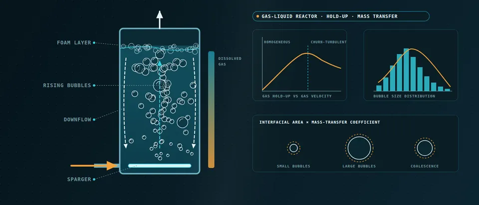
Bubble column CFD predicts how gas spreads through a liquid: hold-up, bubble sizes, circulation and the interfacial area that sets how fast a gas dissolves and reacts. It is a closure-limited model, because drag, lift, bubble-induced turbulence and bubble breakup and coalescence are supplied, not solved, so its answer holds only as far as those closures were checked for your liquid, sparger and scale. We set up that chain around your existing solver, with its validation record.
The pilot column met its target at one gas rate. The plant column is wider, gassed harder, may sit in another flow regime and runs a liquid that is not air and water. A hold-up map is cheap to compute; whether it is right at that scale decides the sparger, the diameter and height, the compressor duty and what you can promise the licensor or customer.
What should bubble column CFD predict beyond gas hold-up?
Syed and colleagues (2017) call gas hold-up the most important design criterion of a bubble column and tie it to bubble size, which sets interfacial area. Depending on superficial gas velocity and column diameter the flow is homogeneous, transitional or heterogeneous, and most closures were built for the first. For a gas that reacts, the quantity to predict is the flux, N = E·kL·a·(C* − CL), with a = 6εG/d32 for spherical bubbles of Sauter mean diameter d32, and the enhancement factor E, which film theory ties to the Hatta number Ha = √(k2DACB)/kL for a reaction first order in gas A and liquid reactant B.
The reaction regime tells you which output to trust. A slow reaction (Ha well below one) runs in the bulk, so liquid volume and mixing matter beside kLa; a fast one, E close to Ha, makes the rate independent of kL, so area is the quantity to get right; an instantaneous one is capped by reactant supply. See our reactor design, multiphase simulation and numerical methods pages.
Which Euler-Euler closures decide a bubble column simulation?
In the Euler-Euler two-fluid model gas and liquid are interpenetrating continua, so everything at bubble scale enters as a closure. Fleck and Rzehak (2019) use one validated baseline set: Ishii–Zuber drag, Tomiyama shear lift, Hosokawa wall lift, Burns turbulent dispersion, virtual mass of one half and a k–ω SST liquid with bubble-induced source terms, run as URANS. Their remark that nearly every closure depends on bubble size is the crux: size is an input, fixed or computed by a population balance.
The lift coefficient changes sign at a critical diameter, quoted by Syed and colleagues as 5.8 mm for air and water after Tomiyama: smaller bubbles drift to the wall, larger ones gather in the core. Their simulated hold-up stayed more peaked than the data, which they suggest may stem from isotropic turbulence; Krauß and Rzehak (2018) point to anisotropic bubble-induced turbulence. The baseline of Fleck and Rzehak reproduced a plume oscillation period but overestimated the upper-level centreline liquid velocity. A finer mesh needed the wall-lubrication force to give sensible near-wall profiles.
- Sparger sets the starting size. Orifice size, plate type and gas rate decide the first bubbles, and near the sparger they can merge into much larger ones. In an Euler-Euler run the inlet size is either an input or the start of a population balance, so the inlet condition is a modelling decision, not a detail.
- Buoyancy against drag. At steady rise drag balances buoyancy, so the drag closure fixes the slip velocity, the residence time of the gas and with it the hold-up. Closures written for single bubbles are corrected for the swarm as the gas fraction grows.
- Lift sends bubbles sideways. Below a critical diameter the lift coefficient is positive and bubbles drift toward the wall; above it the sign flips and they gather in the core. The mean bubble size therefore decides the shape of the radial hold-up profile, not only its average.
- Wall force and dispersion. A wall force pushes bubbles away from the wall, and turbulent dispersion spreads them from dense toward dilute regions. Both interact with the turbulence model and the near-wall mesh, so they are fixed in the template, not tuned case by case.
- Breakup and coalescence. Eddies split large bubbles; liquid drains from the film between colliding ones until they merge. A class-based population balance follows the size classes with empirical kernels that depend on the local dissipation rate, which is why bubble size and turbulence are coupled.
- One constant can flip the profile. In a published air-water case, lowering the Luo coalescence constant shrank the mean bubble across the lift threshold: hold-up moved toward the wall and the axial liquid velocity fell away from the data. Calibrating on hold-up alone can break the flow.
How do you model bubble size with a population balance?
A class-based population balance couples bubble size to the two-fluid model. Syed and colleagues ran one in Ansys Fluent for an air–water column with Luo coalescence and breakup; 14 classes matched 20 or 22. Lowering the Luo coalescence constant from 1.1 to 0.1 cut the mean diameter from 14.9 to 4.94 mm and lifted total hold-up from 5.4% to 7.8%, near the experimental 8%. But 4.94 mm lies below the lift threshold, so bubbles were pushed to the wall and the axial liquid velocity fell away from the data. Hold-up alone would have called the constant a success.
Fleck and Rzehak conclude that coalescence models cannot yet be relied on, partly because size distributions at several heights are rarely measured, so they ran a fixed size. Their deviations appear where coalescence is likely: higher gas flux, a taller column and a sintered-disc sparger that, in the experiments they cite, made much larger bubbles at higher flow. Our rule: calibrate a kernel on size distribution, hold-up and liquid velocity together, then validate on a case it has not seen.
How accurate is kLa from CFD when the gas reacts?
Krauß and Rzehak simulated CO2 absorbing into NaOH in a bubble column. A pointwise model using measured bubble size and gas fraction agreed well with the pH; the same chemistry inside a full Euler-Euler/RANS run gave bubble residence times too short and mass transfer too low. An earlier Euler-Lagrange/LES study agreed with the data to a similar degree for another reason: an enhancement-factor limit used outside its range and no reaction of CO2 with water. Similar agreement, different errors, so we test hydrodynamics and chemistry separately.
kL is the other weak link: that study used a single-bubble correlation, which leaves out swarm and turbulence effects. Hassanaly and colleagues (2025, National Renewable Energy Laboratory) used a Higbie coefficient in an OpenFOAM Euler-Euler model of CO2 in air and water, noting that models beyond air and water remain to be established. To match hold-up and CO2 transfer together they had to raise the breakup rate about tenfold, and the setting that fitted hold-up best was not the one that fitted transfer best.
- Homogeneous regime. At low gas rates in a narrow column the swarm is small bubbles of nearly one size rising in straight lanes with little merging. Most closures were developed here. Whether a column stays in this regime depends on the superficial gas velocity and on the column diameter.
- Churn-turbulent regime. In wide columns gassed harder the population splits into small and large classes. Large bubbles rise fast and meander; small ones are carried round in a strong circulation up the core and down the walls. Pilot slurry-column data show hold-up made of those two classes, so one mean size describes neither.
- Area follows bubble size. For spherical bubbles the interfacial area per unit volume is six times the gas hold-up divided by the Sauter mean diameter. At equal hold-up, halving the mean size doubles the area, so a population-balance error in size is an area error of the same relative size.
- Film and enhancement factor. Liquid-side film theory writes the flux as the enhancement factor E times kL times a times the driving concentration difference. With no reaction E is one; when the dissolved gas reacts inside the film the gradient at the interface steepens and E rises above one.
- Hatta number sets what matters. Ha compares reaction in the film with diffusion across it. A slow reaction needs liquid volume and mixing; a fast one, where E is close to Ha, makes the rate independent of kL and leaves area to get right; an instantaneous one is capped by how fast reactant is supplied.
When is Euler-Euler not enough for a gas-liquid reactor?
Weber and Bart (2017) ran one pseudo-2D column with Euler-Euler and Euler-Lagrange: the Lagrangian cost grew almost linearly with bubble count, and Euler-Euler became cheaper only beyond about 40,000 bubbles in that case, which they sum up as hold-up above 5% or Sauter diameter below 4 mm. A sparger zone or dilute column can be tracked bubble by bubble. For closures no experiment supplies, Roghair, van Sint Annaland and Kuipers (2010) used front tracking, about 20 cells per bubble diameter, on 2–6 mm air bubbles in a periodic box at gas fractions up to 42% to study swarm drag: an interface-resolving run builds the closure, never the column.
How do you scale a bubble column from pilot to plant?
The regime depends on column diameter as well as gas velocity, so matching superficial velocity does not match the flow, and liquid recirculation appears as the column widens. In a pilot slurry column with Fischer–Tropsch catalyst, Inga and Morsi (1999) found churn-turbulent hold-up made mainly of small and large bubbles, with catalyst loading lowering it by removing the small ones: solids change the bubble population, not just the density. Pressure matters twice: solubility follows it, and gas expands as the hydrostatic head falls. We run the pilot geometry first as the validation case, then change diameter, sparger and gas rate with closures and numerics held fixed.
Which bubble column question needs which model?
| Question | Model | What it reports | Limit to state |
|---|---|---|---|
| Hold-up and circulation, homogeneous flow | Euler-Euler, fixed bubble size | Radial hold-up, liquid velocity, plume period | Size is an input; coalescence neglected |
| Bubble size, area, regime change | Euler-Euler with population balance | Size classes, interfacial area, hold-up by height | Kernel constants need size data |
| Gas absorption with reaction | Euler-Euler plus species and enhancement factor | Gas composition and conversion by height | Hydrodynamics, kL and kinetics each need a check |
| Sparger zone, dilute column | Euler-Lagrange | Bubble paths, local merging | Cost grows with bubble count |
| Swarm drag, pair merging | Front tracking or volume of fluid | Drag against gas fraction | Feeds closures; not a column model |
| Sparger and internals loads | Flow pressures mapped to FEA | Stress and deflection | Two-way only if deflection alters flow |
Where does AI help bubble column design, and where does it not?
Hassanaly and colleagues show a useful pattern. A small neural network, trained on 120 Euler-Euler simulations varying coalescence efficiency, breakup efficiency and surface tension, stood in for the solver so Bayesian calibration became affordable, with priors held inside its training range. Higher breakup could be offset by higher coalescence, so a band of parameter pairs fits the data; the calibrated values improved bubble sizes in a stirred tank outside the calibration, though the authors say a firm conclusion needs more data.
That is where AI measurably helps: calibration with an uncertainty range, and a surrogate over gas rate, sparger layout and liquid properties that returns hold-up and area in seconds inside a stated range, gated back to the full model outside it. It does not remove the irreducible model error that parameter tuning left in place, tell you what happens beyond its training range, or replace the pilot data that calibrated it. See our surrogate modelling, hybrid physics-AI and uncertainty quantification pages and surrogate models for CFD and FEA.
A simulated hold-up or kLa is not a performance guarantee
From one hold-up study to a bubble column workflow you keep
The return comes when your engineers can put the next sparger, diameter or liquid through the same chain.
- Physics model. CFD and FEA set up once, as templates: geometry clean-up, mesh, solver settings and post-processing that every later run reuses.
- Validation. Mesh and time-step studies, and comparison with tests or full-scale data, so the model's uncertainty is known before it is trusted.
- Automated runs. Scripted runs over the parameters and operating conditions that matter, on your hardware or in the cloud.
- AI surrogate. A machine-learning model trained on those runs answers in seconds and says how sure it is; low-confidence questions go back to the solver.
- Decision tool. Optimisation, trade-off charts or operating guidance, in a form your engineers and operators use every day.
- Field data. Test, trial and monitoring data flow back to recalibrate the model, so it improves with every project instead of being rebuilt.
- A parametric column template in your existing solver: diameter, sparger, gas rate and liquid properties as parameters; closures, mesh and averaging window recorded once.
- A population-balance set-up with kernels, class count and inlet size distribution under version control.
- A calibration script from your hold-up, bubble-size and kLa data to kernel constants, returning ranges and holding data back for validation.
- A reaction coupling to your kinetics and enhancement-factor model, with a pointwise check on measured size and hold-up (see reactor design).
- A validation record against your pilot data, tolerances set before the run.
- A surrogate with a stated range and a gate to the full model outside it.
- A load hand-off to your structural analysis of sparger and internals (see fluid-structure interaction).
- Handover and training, so your team runs and extends it. See our training and software development services.
Questions engineers ask about bubble column CFD
Euler-Euler or Euler-Lagrange for a bubble column?
Can CFD predict kLa?
Do I need a population balance model?
Is a 2D simulation good enough?
How do surfactants and salts change the result?
If a column or sparger decision is waiting on a hold-up or mass-transfer answer, send us the column and sparger drawing, the gas and liquid with their properties including surfactants or solids, the operating range, and any pilot data: hold-up, bubble size, kLa or conversion. We reply with the model chain we would set up, the validation we would run against your data and what a surrogate could cover. Start with a conversation, or read our multiphase simulation and reactor design pages.