Cold forging simulation: predict die stress and tool fracture before try-out
A punch that cracks at a radius stops the press, costs a tool and hides in the scrap numbers. How tool stress, shrink-fit prestress, workpiece damage and elastic recovery decide tool life, stage count and dimensional accuracy, and where calibration and AI/ML help.
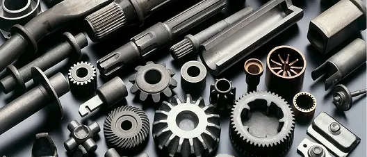
Cold forging simulation predicts, before a die set is made, how the workpiece fills each stage and how much stress the tooling carries, so you can see where a punch or insert will crack and settle stage layout, prestress and radii on screen. The result that matters most is the peak tensile stress in the tool, because cold forging tools often fail by fatigue cracking at a radius rather than by wear.
The scene is familiar. A multi-stage press runs well, then a punch or insert cracks, the line stops and the replacement is cut with the radius the last one had. Behind it sit the costs you track: stages per part, die cost per part, try-out time, scrap, and whether parts hold tolerance without a finishing step. Simulation puts numbers on them while the drawing can still change.
Why do cold forging punches and die inserts crack?
Because the tool is an elastic body loaded close to its capacity, thousands of times a shift. In confined flow, such as forward or backward extrusion, the contact pressure is a multiple of the workpiece flow stress. Inserts are often cemented carbide (WC-Co), which Seo (Scientific Reports, 2022) describes as strong in compression and vulnerable in tension, and that paper names fatigue cracking as the cause of die breakage it studies.
The geometry makes it worse. A bore with internal pressure p, inner radius a and outer radius b carries a hoop stress at the wall of σθ(a) = p (b² + a²) / (b² − a²). It is tension, and it is always larger than p: even an infinitely thick wall only gets down to p. A thicker die does not remove it.
Prestressing does. The insert is pressed into one or more shrink rings with an interference fit, so a compressive hoop stress exists before the press moves and the working load must overcome it before the bore goes into tension. In the fatigue analysis by Joun and co-authors (Materials, 2022), prestressed inserts sit at negative mean stress, while the shrink rings carry tension and are fatigue parts too. In the six-stage ball-stud line of Seo (Scientific Reports, 2022), the shrink fit was 0.1 to 0.14 per cent, varied by stage.
- Contact pressure. Confined flow presses the workpiece against the bore wall with a pressure that is a multiple of its flow stress. Friction, strain hardening and speed decide how high, and the tool feels it as one load cycle per part.
- Insert: strong in compression, weak in tension. A cemented-carbide or tool-steel insert resists compression far better than tension. A bore under internal pressure p carries a hoop tension σθ(a) = p (b² + a²) / (b² − a²), which is always larger than p, whatever the outer radius b.
- Shrink rings and interference. The insert is pressed into a ring, or a pair of rings, with an interference fit. The ring squeezes the insert, so a compressive hoop stress is already there before the press moves and offsets the tension of the working load.
- Stress across the wall. A qualitative hoop-stress profile at one height. Without a ring, the bore wall carries the largest tension. With one, the insert stays near or below zero at peak load and the ring carries the tension, so the ring needs its own fatigue check.
- Failure site: entry radius. Where the bore narrows, the stress concentrates at the radius. Fatigue cracks start here, so the radius value and the mesh at the radius matter more than the average stress in the insert.
- Failure site: punch shoulder. The punch has no ring. Its cycles are mostly compressive, but misalignment bends it and the shoulder radius concentrates stress, which puts tension at the surface where cracks start.
Cracks start where a stress peak meets the cycle count: the radius where the bore narrows, step transitions and the punch shoulder. That is why a corner radius changed by a fraction of a millimetre can matter more than extra wall. The failure you have decides what you compute.
| Failure mode | Where | Compute |
|---|---|---|
| Fatigue crack | Entry and corner radii, transitions, punch shoulder | Local stress history, fatigue allowable with mean stress |
| Overload fracture | Where stress peaks once: double hit, hard blank, misalignment | Peak stress for the worst credible case |
| Wear and galling | Land, bearing surfaces, ejector | Contact pressure and surface expansion |
| Ring fatigue or yielding | Shrink ring bore | Ring stress at assembly and at peak load |
How do you simulate die stress: rigid tool, elastic tool or fully coupled?
Use the lightest model that answers the question. Rigid tools suffice for fill, load and damage in the workpiece. Tool stress needs the die set as an elastic body, usually by applying the workpiece pressure to a finite-element model that includes the shrink fit. For dimensions the pressure depends on how the tool deflects, so the two bodies are solved together.
| Question | Model | Where it breaks |
|---|---|---|
| Does it fill, and what is the load? | Rigid tools, deformable workpiece | No tool stress, no dimensions |
| Will the insert survive? | Pressure applied to an elastic die set with the fit | Stress at a sharp corner grows with mesh refinement |
| Is the prestress right? | Elastic die set, contact at the ring interfaces | Friction at the fit; non-axisymmetric features |
| Will the part hold tolerance? | Elastic tool and workpiece through load, unload, eject | Needs calibrated friction and tool stiffness |
Three inputs decide the trust. Flow stress to the large strains cold forging reaches, from compression tests: Seo (Scientific Reports, 2022) ran theirs to 80 per cent compression. Friction under phosphate and soap or oil, which changes with surface expansion, speed and tool temperature. And heating: at press speed much of the plastic work becomes heat, which lowers flow stress and can break down the lubricant film.
A die-stress figure is a ranking until it is calibrated on your tool-life record
The fatigue model matters as much as the stress. For one sample, Joun and co-authors (Materials, 2022) get minimum high-cycle lives of 45,000 and 100,000 cycles from two mean-stress models, and conclude that die-material tests should include negative mean stress, where prestressed inserts live. See our durability and fatigue life work.
How do you predict ductile fracture in the workpiece?
Surface cracks at a free bulge and internal cracks in an extrusion come from tension acting through plastic strain, so damage criteria integrate both. The widely used one is Cockcroft and Latham's (Journal of the Institute of Metals, 1968): fracture starts when the integral of the maximum principal stress over equivalent plastic strain reaches a critical value, C = ∫ σ1 dε̄.
That value is not a constant of the steel. Kim, Im and Geiger (Journal of Manufacturing Science and Engineering, 1999) tested two criteria on aluminium alloys, found Cockcroft and Latham's gave a more reasonable crack-initiation site in upsetting, and report that the limiting values differ between processes. Calibrate on your steel lot with tests that bracket the process, and read the damage map as a place to look.
Why does the part not match the die? Tool deflection and elastic recovery
Under load the die set deflects, so the cavity at peak pressure is not the drawing's; the part then recovers elastically as pressure falls and again as it leaves the die. Rosochowski (Journal of Materials Processing Technology, 2001) describe a net-shape cold forming procedure that treats both: the interface load distribution drives separate finite-element runs for die deflection and springback, and the die is compensated in CAD.
That is the tolerance-compensation loop. It needs calibrated friction and flow stress, and measured dimensions fed back after each trial, not just pass or fail.
How many cold forging stages does the part need?
As few as the tools and the steel allow. Volume is conserved, so a sequence moves the same steel through shapes, and each stage has a reduction. A larger reduction saves a stage, a die and a station, and raises die pressure and strain hardening. A smaller one lowers tool stress and adds a stage. Judge each candidate with tool stress, damage and load together.
- Slug and volume. A sheared slug sets the volume. Volume is conserved through every stage, so each stage redistributes the material of the one before it.
- Reduction stage. Forward or backward extrusion cuts the cross-section. A larger reduction raises both die pressure and strain hardening, so stage design trades reduction per stage against tool stress and the number of stages.
- Upset stage. Heading gathers material into the head. The free bulge is in circumferential tension, the classic place for surface cracks, so workpiece damage is checked here.
- Final form. The closing stage fills corners, recesses and features. Pressure and load peak as the cavity fills, so the fill check and the tool-stress check use the same moment of the stroke.
- Checks at every stage. The same four after each stage: fill without laps or folds, peak tool stress against the fatigue allowable, workpiece damage against the calibrated limit, and press load against capacity. A failed check sends the sequence back before a die is cut.
- Between stages. Strain hardening raises the flow stress from stage to stage and the lubricant film can be used up. Where the sequence needs it, annealing and fresh lubrication restart the budget, at the price of an extra operation.
- Dimensions and compensation. Tool deflection under load and elastic recovery after ejection move the part away from the cavity dimension. Measure the part, compare it with the drawing and correct the cavity.
No stage passes on fill alone. Each clears fill, tool stress, damage and press load, and hands on a preform the next stage can centre and fill. Where hardening or a spent lubricant film blocks the next reduction, the sequence earns an anneal and fresh lubrication, at the cost of an operation. See our cold forming simulation page, within our metal forming simulation work.
Where does AI/ML help cold forging simulation, and where does it not?
AI/ML earns its place around the physics model. Each use has a limit we state when we build it.
| Use | What it does | Limit |
|---|---|---|
| Surrogate of peak die stress and fill | Trained on planned runs over stage geometry, reduction and prestress; ranks sequences in seconds | Valid inside the sampled range; the radius still gets a solver check |
| Bayesian calibration of friction and flow stress | Fits both from instrumented trials and returns a distribution | Only as good as the trial data; friction drifts |
| Sequence and tolerance optimisation | Finds layouts that hold across hardness, lubrication and alignment scatter | Needs measured scatter |
| Anomaly gate on punch force | Flags drift in the force trace before damage accumulates | Detects change, not cause |
On monitoring, Seo (Scientific Reports, 2022) measured forming load with a piezo sensor in the punch block, converted it to a stress estimate with a linear model and applied Miner's rule; the error against field die life fell from up to 20 to about 7 per cent in that line. It is one line, but it shows that the press signal carries information the simulation cannot.
AI/ML does not replace fatigue testing of a new tool steel or carbide grade. A surrogate learns from simulations, and simulations contain only the fatigue data you gave them, so a new grade needs new data, including the negative-mean-stress region. The discipline is a stated range, held-out validation and a route back to the solver. See validating AI surrogates, the surrogate-model primer, and our surrogate modelling and uncertainty quantification pages.
From one broken punch to a die-set workflow you keep
A single study answers the tool that broke. The larger return comes when material data, die-set model and compensation rules are something your process engineers run for every new part, so the next stage layout or prestress costs hours, not a tool.
- Physics model. CFD and FEA set up once, as templates: geometry clean-up, mesh, solver settings and post-processing that every later run reuses.
- Validation. Mesh and time-step studies, and comparison with tests or full-scale data, so the model's uncertainty is known before it is trusted.
- Automated runs. Scripted runs over the parameters and operating conditions that matter, on your hardware or in the cloud.
- AI surrogate. A machine-learning model trained on those runs answers in seconds and says how sure it is; low-confidence questions go back to the solver.
- Decision tool. Optimisation, trade-off charts or operating guidance, in a form your engineers and operators use every day.
- Field data. Test, trial and monitoring data flow back to recalibrate the model, so it improves with every project instead of being rebuilt.
- A validated material and friction library for your steels and lubricants: flow stress to large strain, damage limit, uncertainty.
- A parameterised die-set model: insert, rings, interference, radii and punch as inputs, automated stress checks at each radius, and a report that reads the same for every part.
- A tolerance-compensation loop that takes measured parts, separates tool deflection from recovery and proposes a corrected cavity.
- A surrogate with a stated range for stage layout and prestress, with a route back to the solver.
- A punch-force gate tied to your tool-life record.
- Training and handover, so your engineers extend it themselves. See our training and software development services.
Questions engineers ask about cold forging simulation
How does a shrink ring extend die life?
Can simulation predict tool life?
Is a rigid tool model enough?
How many stages does a cold forged part need?
Which software do you use?
If tool breakage, stage count or tolerance is on your desk, send us one part number with its drawing and tolerances, the material card or lot certificate, the stage sequence with tool drawings (insert, rings, interference), the lubricant, and the tool-life record with the failed tools and where they cracked. A punch-force trace helps most. You get back a written diagnosis of the failure mechanism, the model level it needs and a plan for the workflow. Start with our consulting service, or a conversation.