Roll forming and ring rolling simulation for fewer trials and fewer rejects
Roll forming and ring rolling shape the part gradually, over many stands or many revolutions. How edge strain, feed curves and guide rolls cause bow, twist and out-of-roundness, why the simulations take so long, and how validated surrogates turn them into a design tool.
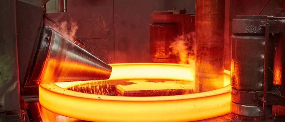
Roll forming simulation predicts, stand by stand, how a strip becomes a section and where the strain that causes bow, twist and edge wave builds up. Ring rolling simulation does the same for a ring that grows over many revolutions between a main roll, a mandrel and guide rolls. Both shape the part through many small contacts, so full models are long and contact-heavy, and the practical route is a validated set of runs plus a surrogate your engineers can query in seconds.
A new high-strength section reaches the line with the flower of the last section that looked similar. The first metres bow, the stands are shimmed, the coil is run again, the next one is scrapped. On a ring mill the ring comes out slightly out of round, and the answer is more machining allowance. Wang et al. (2022) describe roll forming practice as relying on experience, with edge waves corrected by trial and error that consumes material and time, and Surdacki and Gontarz (2026) note that ring rolling lacks an approach for minimising out-of-roundness at the design stage. You pay in line set-up time, roll tooling cut before the pass design is proven, rejects, material use and slow quotations. Our roll forming and ring rolling simulation page, within our metal forming simulation work, describes the capability; this article explains the mechanisms and how the answers become permanent.
Roll forming simulation: where do bow, twist and edge wave come from?
When a flange rises, the strip edge leaves the pass line and travels a longer path than the centre of the web, so it is stretched along the rolling direction, as Wang et al. (2022) describe. To first order the stretch is ε ≈ ½(Δz/L)², where Δz is the rise of the edge between two stands and L the stand spacing. Large angle steps punish the edge, quadratically. This is a scaling argument, not a prediction, because the strip relieves part of the strain elastically between stands.
Peak edge strain along the line is the number to watch. Where it exceeds what the strip can carry, the edge yields or buckles, and strain that is uneven across the width is released when the strip leaves the last stand. Ma et al. (2026) simulate asymmetric corrugated aluminium channels and describe this: longitudinal strain accumulates pass by pass and appears as bow when released. Their literature review shows effects changing sign with the section: one study found high-strength steel bowing more than low-carbon steel in a U-channel, another found higher yield strength going with less bowing.
- The flower pattern. One cross-section per stand, each adding a little bend angle until the section is formed. Pass design is the choice of those angles, their order, the stand spacing and the roll diameters, which is why there are so many variables to try.
- The edge travels further. As a flange rises, the strip edge moves away from the pass line and covers a longer path than the centre between two stands. To first order the edge is stretched by about ½(Δz/L)², with Δz the rise of the edge between stands and L the stand spacing. It is a scaling argument; elastic relief and contact change the real value.
- Peak edge strain. Followed through the stands, the longitudinal strain at the edge builds, peaks where the flange rises fastest and relaxes. Where the peak exceeds what the strip can carry elastically, the edge yields or buckles. This peak is the design indicator.
- Stand spacing. The distance between stands gives the strip room to relieve strain. Published finite-element studies disagree on how much it matters, because the answer depends on the section and the model set-up, so it is computed for your section instead of applied as a rule.
- Springback. After the last stand the strip unloads and the angle opens. The elastic strain stored at stress σ is σ/E, so a high-strength steel with a similar modulus recovers more, and the flower has to over-bend to compensate.
- What the strain leaves behind. Strain that is uneven across the width is released when the strip leaves the rolls: bow along the length, twist in asymmetric sections, and waves along the edge. These are the rejects the line pays for.
Stand spacing shows how far a rule of thumb travels. In a deep stainless-steel section, Wang et al. (2022) found larger spacing lowering the peak edge strain, within a suitable range. Studies reviewed by Ma et al. (2026) report that spacing had the least effect on bow in one case and was critical for bow and springback in V-section advanced high-strength steel (AHSS) in another. So these effects are computed for your section.
Springback adds a second error. The elastic strain stored at stress σ is σ/E, and steels share almost the same E, so the stronger the steel, the larger the recovery. Wang et al. (2022) review work reporting springback rising with yield strength, so an AHSS flower must over-bend further. The question for the simulation is whether bow, twist and angle at the exit stay inside the tolerance, whether the customer's or a standard such as EN 10162:2003 for cold-rolled sections made on roll-forming machines. For sections that become crash structures, see crash simulation you can trust.
Ring rolling process design: what makes a ring grow stably, and round?
In radial-axial ring rolling a driven main roll presses the outside of a pre-formed ring while an idle mandrel inside it is fed toward the main roll. The wall thins in the nip and the ring grows. Conical axial rolls control the height; guide rolls on the outside keep the ring on its path. With no slip the ring turns at the main roll's surface speed and each revolution thins the wall by about Δh = vf·T, with vf the mandrel feed speed and T the time for one revolution, as in Meng et al. (2014). Volume is conserved, so π·Dm·h·H = V: mean diameter, wall thickness and height trade off against each other.
Feed per revolution has to stay inside a window. Meng et al. (2014) restate, for a conical ring, the plastic-penetration and biting-in conditions of Hua et al.: a lower bound so the deformation reaches through the wall, and an upper bound set by the friction angle so the ring is drawn in. Both move as the ring grows; a constant outer-radius growth rate is the strategy they adopt. Xie et al. (2023) describe guide rolls as preventing the ring from swinging, tie instability to roundness error, eccentricity and vibration, and split the feed curve into initial, rapid, steady and slow stages.
- Main roll. The driven roll on the outside of the ring. With no slip the ring turns at its surface speed, so the time T for one ring revolution is the circumference divided by that speed, and it lengthens as the ring grows.
- Mandrel and feed. The idle mandrel inside the ring is pushed toward the main roll at feed speed v_f. The wall is thinned by about Δh = v_f·T each time the ring turns once, so the feed curve and the roll speed together set the reduction per revolution.
- The nip. Feed per revolution has to stay inside a window. Too little and the deformation does not reach through the wall; too much and the ring is no longer drawn in, a limit set by the friction angle and the roll radii. The window moves as the ring grows.
- Guide rolls. Idle rolls on the outside stop the ring swinging and keep its centre on the line. Their position is a design variable: in one radial rolling study, the position of the calibrating roll had the largest effect on out-of-roundness of the parameters tested.
- Axial rolls. In radial-axial mills, conical rolls press the top and bottom faces to control the ring height. Without that control the section can distort and the ring can show the fishtail defect.
- Growth by volume conservation. The material volume is fixed, so as the wall thins the diameter grows: mean diameter × wall thickness × height stays about constant. Feed curves usually start gently, hold a steady growth rate in the middle and slow down again at the end.
- Out-of-roundness. Measured as O = (D_max − D_min) / D. Feed, roll speed, guide-roll position, billet temperature and mill stiffness all act on it, and published studies do not agree on the effect of feed speed, which is why it is simulated for your mill.
Out-of-roundness, O = (Dmax − Dmin) / D, is the defect that costs material. Surdacki and Gontarz (2026) list billet geometry, forming speed, rolling strategy, material, force, temperature and mill stiffness as influences. Among the earlier studies they review, one finds a higher growth rate lowering ovality, another a large reduction per revolution raising it. In their own radial rolling experiments the calibrating-roll position had the largest effect, with an optimum that moved with feed speed, a higher billet temperature increased ovality, and no condition gave a perfect circle. Gontarz et al. (2023) find that a higher feed speed reduces the cross-section distortion called fishtail.
Hot rings add a thermal history: studies reviewed by Meng et al. (2014) report more uniform strain and temperature at higher mandrel feed and initial temperature, and microstructure follows. See our thermal analysis work.
Why do full roll forming and ring rolling simulations take so long?
A roll forming model needs strip long enough to sit in two stands at once (Wang et al. (2022) used more than twice the stand spacing), a front end that behaves unlike steady running, contact at every stand and a fine mesh at every bend. A ring must turn many times through a small, moving contact zone.
In an explicit solver the stable time increment is limited by the smallest element, Δt ≲ Le/c, c = √(E/ρ). For a 1 mm element in steel c is about 5 km/s, so Δt is of the order of 10-7 s and a cycle of tens of seconds needs of the order of 108 increments. Engineers cope with mass scaling (a factor of 50 with ALE remeshing in Meng et al. (2014)), symmetry, sub-models of one stand or the nip and, where offered, steady-state or Eulerian formulations with material flowing through a fixed mesh. Each trades something: mass scaling adds artificial inertia, which matters when inertia drives ring ovality, so we check that kinetic energy stays a small fraction of internal energy.
| Question | Fast level | Full level | Limit |
|---|---|---|---|
| Is this flower plausible? | Edge-path estimate per stand pair | 3D shell model of all stands, rigid rolls | Needs a calibrated material card |
| Will the section bow, twist or spring back out of tolerance? | Rank designs by peak edge strain and its imbalance | Full model released after the last stand | Asymmetric sections break rules built on symmetric ones |
| Is the ring feed curve inside the bite and penetration window? | Kinematic model with volume conservation | 3D thermo-mechanical explicit model with guide and axial rolls | Window depends on friction and temperature |
| Will the ring come out round and filled? | No reliable shortcut | Full model over the whole cycle | Long runs; check mass scaling |
Calibrate against one measured section or ring before ranking any parameter
Where does AI/ML help with pass design and feed curves, and where does it not?
AI/ML sits around the solver, and the solver stays the reference. The aim: a process or sales engineer asks what happens to bow if the third-stand angle and the spacing change, and gets an answer with its range, not a week-long run.
| Use | What it does | Limit |
|---|---|---|
| Surrogate of defect indicators | Predicts peak edge strain, bow, twist and springback, or out-of-roundness and growth-rate window, from pass, feed, guide-roll and coil-strength inputs, trained on a designed set of full runs | Valid only inside the sampled section family and ranges |
| Active learning | Picks the next expensive run where the surrogate is least certain or nearest a limit | Bounded by the cost of each full run |
| Calibration from line trials | Fits friction and hardening to a measured section, ring history or roll force | Friction barely moved edge strain in the two roll forming studies cited, so bow records cannot identify it |
| Anomaly gate | Compares each measured section or ring with its prediction and flags drift | Needs your line measurements; it flags, it does not diagnose |
The limit no network removes is extrapolation. A new section type, an asymmetric section or a material with no simulation coverage lies outside the training set. The studies reviewed by Ma et al. (2026) include one showing strain non-uniformity amplified in asymmetric sections, so defect models built for symmetric profiles do not transfer, and a surrogate behaves the same way. We return such cases to the solver and say so. For the method, see our articles on surrogate models for CFD and FEA and validating AI surrogates, and our pages on surrogate modelling and validation and benchmarking.
From one trial line to a pass-design workflow you keep
A single study answers the section or ring it was run for. The larger return comes when pass design and feed curves become something your own engineers run for every enquiry, so the next quotation starts from a validated template. We build roll forming and ring rolling work this way.
- Physics model. CFD and FEA set up once, as templates: geometry clean-up, mesh, solver settings and post-processing that every later run reuses.
- Validation. Mesh and time-step studies, and comparison with tests or full-scale data, so the model's uncertainty is known before it is trusted.
- Automated runs. Scripted runs over the parameters and operating conditions that matter, on your hardware or in the cloud.
- AI surrogate. A machine-learning model trained on those runs answers in seconds and says how sure it is; low-confidence questions go back to the solver.
- Decision tool. Optimisation, trade-off charts or operating guidance, in a form your engineers and operators use every day.
- Field data. Test, trial and monitoring data flow back to recalibrate the model, so it improves with every project instead of being rebuilt.
- Parametric templates: a flower generator (angle per stand, spacing, roll diameters) and a ring-rolling template (blank, rolls, feed-curve stages, guide-roll positions).
- A validation record of predicted against measured bow, twist and section shape, or ring diameters and out-of-roundness, with the deviation stated.
- Automated batches over the pass and feed variables on your HPC or in the cloud.
- A validated surrogate with its range written down, so sales and engineering screen a section or feed curve in seconds and anything outside the range returns to the solver.
- An anomaly gate and recalibration: each coil or ring is compared with its prediction, and friction and material are refitted when coils, rolls or settings change.
- Training and handover, so your engineers extend it themselves: our training and software development services.
Questions engineers ask about roll forming and ring rolling simulation
What causes edge wave in roll forming?
Can simulation predict bow and twist?
What makes a rolled ring out of round?
Which software do you use?
If a section bows or a ring mill loses steel to machining allowance, send us what you have. For roll forming: the section drawing, flower, stand spacing, roll diameters, coil certificate and your measured bow, twist or edge-wave record. For ring rolling: preform and ring drawings, roll and mandrel diameters, the feed curve, guide-roll settings and measured diameters of a few rings. You get a written diagnosis of the limiting indicator, the analysis level it needs and a workflow plan. Start with a conversation, or read about our consulting service.