Dust explosion venting design with CFD and FEA beyond NFPA 68 and EN 14491 sizing
A vent area from NFPA 68 or EN 14491 answers one question. Panel mass, vent ducts, recoil and flame outside the vent answer others. CFD and FEA, built into a workflow your team keeps, show what the vessel, the duct and the supports actually see.
Dust explosion venting protects a vessel by opening a relief area early enough that the deflagration pressure stays below what the equipment can carry. NFPA 68 and EN 14491 give the vent area as a correlation. We test it with CFD and FEA against your vessel, panel, duct and supports, and return the pressure and thrust histories the structure must survive, in a workflow your team keeps.
Picture the drawing review for a spray dryer in a food plant, a dust collector on a pharmaceutical line or a powder hopper in a chemical works. The vent calculation asks for a large panel, the only suitable wall faces a walkway, so the relief runs through a duct with two bends, and the vessel stands on a frame sized for weight. Does the duct choke the vent? What force reaches the frame when the panel lets go? Or should the vessel be suppressed, isolated or built to withstand the pressure? Each answer moves steel, floor space or delivery dates, and each is usually settled by one conservative number.
What does dust explosion venting have to do?
A vent is a deliberate weak point. When the pressure inside reaches the panel's opening pressure, the panel releases and the burning gas leaves. Pressure rises while combustion makes gas faster than the vent can pass it, and peaks where the two rates are equal. That peak, the reduced pressure Pred, is what the vessel must carry.
NFPA 68, Standard on Explosion Protection by Deflagration Venting, applies, in its own words, to “the design, location, installation, maintenance, and use of devices and systems that vent the combustion gases and pressures resulting from a deflagration within an enclosure so that structural and mechanical damage is minimized” (NFPA 68 page, 2023 edition). EN 14491:2012 covers dusts: vent sizing, flame and pressure effects outside the enclosure, recoil forces, the influence of vent ducts and hybrid mixtures, but no rules for detonations or runaway exothermic reactions. EN 14797 covers venting devices, EN 14460 explosion-resistant equipment, EN 15089 isolation, EN 14373 suppression and EN 14994 gas explosion venting.
The hazard is real. The US Chemical Safety Board's 2006 study identified 281 combustible dust incidents between 1980 and 2005 that killed 119 workers and injured 718, in food, chemical, paper, pharmaceutical and metal processing (CSB page).
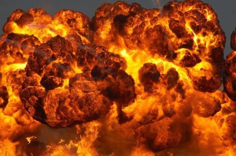
Why is vent sizing harder than a formula suggests?
The dust enters the correlation through two test values: Pmax and the deflagration index KSt = (dp/dt)max · V1/3, the cubic law that scales a pressure-rise rate measured in a 20-litre sphere or a 1 m³ vessel to any volume. An open-access Powder Technology study of the dispersion in the 20-litre vessel (Islas et al.) notes that turbulence at ignition changes the result and that the cubic law holds for specific turbulence levels.
A correlation is also a fit to experiments with a stated range. The authors of an 11.5 m³ corn starch study (Huang, Bloching and Lipatnikov) read the main vent-area equations of EN 14491:2012 as requiring a length-to-diameter ratio between 1 and 20. They note that elevated initial pressure is considered in neither EN 14491 nor EN 14994, and that neither NFPA 68 (2018) nor EN 14491 applies above 10,000 m³. They add that for corn starch, the best-studied dust, data on particle size, agglomeration and laminar flame speed is limited, so dust is a harder CFD target than gas.
How is explosion venting usually designed, and where does it break?
The usual route is correlation in, vent area out, then a certified panel from a supplier. It suits a compact vessel inside its range and breaks in four places.
- Ducts and obstacles. A duct throttles the outflow, so pressure climbs further before the gas gets out, and flame entering it can burn the mixture pushed ahead. EN 14491 covers vent-duct influence; a route with bends or a filter in the way needs its own geometry.
- The panel. A cover has mass and an opening pressure. A heavier one opens later, so pressure climbs further before relief starts.
- Recoil. The jet pushes back. To first order the quasi-steady thrust is F = ṁue + (pe − pa)Ae at the vent exit, opposite to the jet. A frame sized for weight meets it as a pulse, and a pulse faster than the frame's natural period loads it differently from the same peak applied slowly.
- The event after the vent. In the 11.5 m³ test, a St1 corn starch with KSt of 200 bar m/s ± 15 % vented through a 0.5 m² opening closed by a 70 µm aluminium foil. The pressure record had four stages: a closed-vessel rise, a drop and slow rise after the foil ruptured, a rapid second rise while the burning cloud grew outside the vessel, then a decay.
- Dust cloud and ignition. Fine particles suspended in air and lit at one point. How even the cloud is, how turbulent it is and where it ignites decide how fast the flame grows. Real clouds are rarely uniform.
- Flame front and pressure. Burnt gas expands and the pressure loads every wall. It keeps rising while combustion makes gas faster than the vent can pass it.
- Vent panel. The cover opens at its set pressure. Its mass and opening pressure decide when relief starts, so they belong in the model and not in a footnote.
- Vent duct. A duct throttles the outflow, so the pressure inside climbs higher before the gas gets out, and flame entering the duct can burn the mixture pushed ahead of it.
- Outside the vent. Burning dust and gas meet air outside: a plume, a pressure wave and, in one published test record, a second pressure rise. Whatever stands in the path is part of the load case.
- Reaction force. The jet pushes back. Thrust is the momentum flux plus the pressure difference times the exit area, opposite to the flow, and it reaches the vessel, the duct bend and the supports as a pulse.
What does CFD add to the vent-sizing correlation?
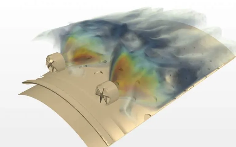
The correlation answers how much area; the simulation answers what happens in this plant when the panel opens. We solve the vented deflagration in your existing CFD solver, such as Ansys Fluent: compressible and turbulent, with the dust flame treated as a premixed turbulent flame, the analogy the studies above rely on. The panel is an event with mass and opening pressure, and the duct and the volume outside are in the domain. The outputs are pressure and thrust histories and the flame extent outside. Gas and vapour deflagrations in enclosed equipment follow the same route, within our blast, explosion and fire and reacting flows and combustion work.
Done properly, this is verification and validation, not a picture: mesh and time-step studies, then mass and energy balances through the venting. In the 11.5 m³ study, turbulence was not measured, so it was adjusted until the computed closed-vessel pressure matched the test, and the model was judged on the venting phase. Seven turbulence models gave different pressure histories, and the conventional flame model under-predicted the overpressure until an acceleration term with a tuned activation time was added. Our record says which inputs were calibrated, on which test, and which were predicted blind.
We also simulate the test behind your inputs. A dispersion model of the 20-litre sphere, like the one in the Powder Technology study, shows fine particles gathering near the wall while coarser ones mix more evenly, so the KSt input is carried as a range.
Then the loads go to the structure. Wall pressure and vent thrust are mapped, as time histories, onto the finite element model of vessel, nozzles, supports and platform in your explicit solver, such as LS-DYNA or Abaqus, and the frame and anchors are checked against the pulse they receive and the response limits your design basis allows. See our chemical, petrochemical and oil and gas applications and chemical processing work.
- Closed-vessel rise. Before the panel opens, pressure rises as the cloud burns inside a closed vessel. Dust, turbulence and ignition position set the rate.
- Panel opens. Pressure falls as the vent passes gas, then recovers. Panel mass and opening pressure decide when this happens and how steeply.
- Rise outside. A published 11.5 m³ corn starch record shows a second, rapid rise while the burning cloud grew outside the vessel. The curve here is qualitative; its shape depends on the case.
- One value. A vent-sizing correlation returns a reduced pressure. It carries no timing, no duct effect and no force, so on its own it cannot feed a structural check.
- Thrust history. Thrust exists only once the vent is open and follows the outflow. Its rise rate and duration matter as much as its peak.
- Frame response. The support frame behaves as a mass on a spring with damping, m·ẍ + c·ẋ + k·x = F(t). Its response depends on how F(t) compares with the frame's natural period.
- Same peak, different pulse. A short pulse and a long pulse of the same peak load a frame differently, so the structure needs the duration as well as the peak force.
| Question | What the standard covers | What simulation adds | Decision it supports |
|---|---|---|---|
| Vent area, compact vessel | NFPA 68 and EN 14491 vent sizing | A cross-check of the inputs | Vent area, opening pressure |
| Vent duct, bends, internals | EN 14491 lists vent-duct influence; main equations L/D 1 to 20 | Flow and pressure through your route | Duct route and diameter |
| Recoil and flame outside | EN 14491 lists recoil forces and outside effects | Thrust history onto the structure; plume extent | Frame, anchors, vent location |
| Suppression instead of venting | EN 14373: tested against defined explosions, in closed enclosures | Pressure rise to activation; the tested envelope governs | Vent, suppress or contain |
| Isolation between equipment | EN 15089: stops pressure wave and flame, or flame only, in connecting ducts; generally not burning powder | Flame and pressure arrival along the line | Isolation point |
| Outside the correlations | Elevated pressure not considered in EN 14491 or EN 14994; NFPA 68 (2018) and EN 14491 not above 10,000 m³ | Calibrated CFD with its validation record | Vent, suppress or strengthen |
A simulated vent area is not an approved vent area
Where does machine learning help dust explosion protection, and where does it not?
- A surrogate over the vent design space. Inputs: vent area, opening pressure, panel mass, duct length and diameter, ignition position and the dust's KSt range. Outputs: Pred, the time of the peak, thrust peak and impulse. Planned CFD runs train it, the correlation's value is the baseline it corrects, and the optimiser works in seconds.
- Calibration of what nobody measured. Turbulence level and effective burning rate are fitted to your test pressure records, and the spread of the fit is carried forward as a range.
- Run triage. Balances, pressure before the panel opens and mesh sensitivity are checked automatically, and a failed run never enters training.
It does not replace the physics at the edges. A surrogate trained on compact vessels says nothing about a duct geometry it has not seen, it inherits every error in the CFD, and it cannot supply KSt and Pmax, which come from tests. A stated range and a gate send anything outside it to the full model. See surrogate models for CFD and FEA and validating AI surrogates with uncertainty.
From one vent study to an explosion-protection capability you keep
The return comes when your own engineers can put the next vessel, duct route or dust through the same set-up without rebuilding the model or the checks.
- Physics model. CFD and FEA set up once, as templates: geometry clean-up, mesh, solver settings and post-processing that every later run reuses.
- Validation. Mesh and time-step studies, and comparison with tests or full-scale data, so the model's uncertainty is known before it is trusted.
- Automated runs. Scripted runs over the parameters and operating conditions that matter, on your hardware or in the cloud.
- AI surrogate. A machine-learning model trained on those runs answers in seconds and says how sure it is; low-confidence questions go back to the solver.
- Decision tool. Optimisation, trade-off charts or operating guidance, in a form your engineers and operators use every day.
- Field data. Test, trial and monitoring data flow back to recalibrate the model, so it improves with every project instead of being rebuilt.
- A parameterised vented-vessel model in your CFD solver, with vessel, panel, duct, ignition and dust in a case file and not in the mesh.
- The correlation, scripted beside it from your licensed copy of the standard, so each case shows its difference from the NFPA 68 or EN 14491 value.
- A load-transfer script that maps pressure and thrust histories onto your structural model and reports the response against your design basis.
- A validation record against your last vent trial or dust test: what was calibrated, what was predicted, tolerances and results.
- An automated run set and a gated surrogate with a stated range.
- Handover and training, so your team extends it. See our training and software development services.
Questions engineers ask about dust explosion venting
How is the vent area for a dust explosion calculated?
What is K<sub>St</sub>?
Can CFD replace the vent-sizing standards?
Does a vent duct change the vent area you need?
What do you need from us to start?
If a vent, a duct or a frame is holding up a release, send us the vessel and vent drawing, the duct route and support layout, your dust test report (Pmax, KSt, particle size distribution, moisture) and the vent calculation you have. We will reply with how we would set up and validate the model, which inputs we would calibrate and which would be predicted, and where a surrogate's range would end. Start with a conversation.