Structural fire analysis of pipe racks, vessels and supports in pool and jet fires
A leak ignites, and the decision is which members need fireproofing and how long the rest will stand. Coupling a CFD fire field to thermal-structural FEA gives steel temperature, strength loss and time to failure per member and per fire, and a surrogate screens the scenario set.
Structural fire analysis calculates how hot the steel of a pipe rack, vessel or support gets in a pool or jet fire, how much strength it loses on the way, and how many minutes pass before it can no longer carry its load. We build that chain, from a CFD fire field to a thermal-structural FEA model and a surrogate that screens fire scenarios, as a workflow your engineers run on your existing solvers.
A fuel-gas line on the lower level of a pipe rack leaks and ignites. The rack must hold its process lines until isolation and depressurising take effect, so the review asks which columns and beams need passive fire protection, and how much. Coat every member and cost and schedule absorb it. Coat too few and the first fire to engulf the rack decides for you. Without a time to failure per member and per fire, the safe-looking answer is to coat everything.
What does structural fire analysis have to answer?
For each member and each credible fire, three things: the steel temperature over time, the load the hot member must carry, and the temperature at which it can no longer carry it. Where the first meets the third is the time to failure, compared with the time your isolation, depressurising and emergency response need. If it is long enough the member needs no protection. If not, the model sizes the protection and shows how far it must extend.
Bare steel is fast. The JRC Eurocodes workshop material on fire resistance of steel structures to EN 1993-1-2 works through a six-level steel office building with an R60 requirement: a bare IPE 360 secondary beam, heated on four sides, reaches its critical temperature of 667 °C after 17 minutes of ISO 834 standard fire. The same material gives the effective yield-strength reduction factor as 0.78 at 500 °C and 0.47 at 600 °C. And the critical temperature is not one number: the four bare members of that frame have critical temperatures between 560 and 667 °C, because each carries a different share of its capacity in the fire.
Why is a real process fire harder than the standard fire curve?
Steel responds to the heat flux at its surface, not to the fire's temperature, and that flux depends on the surface: qnet = ε(qinc − σTs4) + h(Tg − Ts): radiation absorbed less radiation emitted, plus convection from the hot gas. Incident radiation comes from a sooty flame of a given size and distance, so it differs from member to member. A furnace test controls one gas temperature around a specimen. A pool fire engulfs a rack from below, radiates unevenly and leans with the wind.
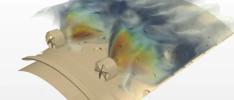
A jet fire adds momentum and locality: it is narrow, directional, and strikes a leg, skirt or column at one spot. The ISO 22899-1 jet fire test describes how passive fire protection behaves in a jet fire under specified conditions, and its scope states that complete I-beams and columns cannot be tested to it, because they disrupt the characteristics of the jet. The shape of the member changes the fire that hits it, which a CFD model with the real geometry can resolve.
Then the steel. A thin section at uniform temperature heats by a lumped balance, dθ/dt = ksh(Am/V) qnet / (caρa), where Am/V is the section factor, the heated surface per unit volume of steel: slender members heat faster than heavy ones. Thick walls, insulated members and joints need conduction through the thickness. On a vessel, the wetted wall stays near the liquid temperature, the vapour-space wall has little cooling from inside, and pressure rises as the contents warm. A relief valve limits pressure. It does not cool the wall.
- Pool fire. A burning liquid pool engulfs the equipment above it. The flame is large and sooty, so most of the heat arrives as radiation, and wind tilts the flame and moves the hottest zone from one member to the next.
- Radiation and hot gas. Radiation travels in straight lines from the flame to every surface that can see it, and a buoyant plume of hot gas washes the structure by convection. Together they set the heat flux at each steel surface, and neither is uniform.
- Bare and protected members. The member nearest the fire heats first, at a rate set by its section factor, the heated surface per unit volume of steel. A fireproofing layer slows the heat flowing in, but the layer, its joints and its edges have to survive the fire as well.
- Wetted and vapour-space wall. On a vessel, the wall in contact with liquid is held near the liquid temperature, while the wall in the vapour space has little cooling from inside and heats towards the flame. Internal pressure rises as the contents warm, so the hot wall carries more load with less strength.
- Jet fire on a support. A leak that ignites can form a narrow, high-momentum flame that hits a skirt, leg or column directly. It heats one spot far faster than a pool fire heats the whole member, and the shape of the member changes the flow around it.
- Heat balance at the surface. Steel responds to the net heat flux: radiation absorbed less radiation emitted, plus convection from the gas. The surface temperature is part of the equation, which is why the fire model and the structural model must agree on how the exposure is handed over.
How are pipe rack and vessel fires usually assessed, and where does that break?
Typical assessments use a prescribed heat flux or standard curve for every member, a lumped steel-temperature spreadsheet, and a fire test rating for the protection product. API RP 2218 gives guidance on selecting, applying and maintaining fireproofing to limit fire-related property loss from pool fires, with an informative annex on jet fire considerations. Each tool fits the question it was built for. Four things go wrong beyond it.
- One flux for every member. It over-protects steel outside the flame and under-protects the member the jet hits.
- The standard curve. EN 1991-1-2 states in its scope that its methods apply to buildings with a fire load related to the building and its occupancy. Its nominal curves, the hydrocarbon curve included, are still one gas temperature around a member, not a pool or a jet.
- Test-only protection. HSE research report RR1120 (2017) examined whether the jet fire test represents severe release scenarios. Its summary finds the standard test representative of most but not all, says that simply raising the heat flux may not give a more onerous test, and calls for large-scale testing to show how products respond to actual fire events.
- A study that cannot be rerun. A CFD fire run is post-processed by hand into a spreadsheet, and when the layout changes the study starts again.
| Question | Fire exposure | Structural model | Decision it supports |
|---|---|---|---|
| Pipe rack under a pool fire | CFD flame with soot and radiation, handed over as an adiabatic surface temperature | Thermal model of members and protection, loaded check at temperature | Which members need protection, how thick, how far |
| Column, leg or skirt hit by a jet fire | Jet CFD with the real member geometry | Local heating through the thickness, check with restraint | Whether the support holds until isolation and depressurising |
| Pressure vessel in a fire | Exposure on wetted and vapour-space wall | Wall temperature, strength at temperature, internal pressure | Time to wall failure against relief and depressurising |
| Specifying passive fire protection | Scenario set, not the standard curve alone | Protected-member thermal model, thickness sweeps | Thickness and extent per member, what the test must cover |
| Many members, many fire scenarios | Planned CFD runs | Surrogate trained on the chain, with a gate | Which cases get a full run |
How do you couple a CFD fire field to thermal-structural FEA?
The coupling variable matters. Passing the CFD heat flux to the structural model looks obvious, but that flux was computed with the CFD model's own surface temperature, not the steel's. The better interface is the adiabatic surface temperature from the NIST paper by Wickström, Duthinh and McGrattan: the temperature of a perfectly insulating surface in the same exposure, defined by ε(qinc − σTAST4) + h(Tg − TAST) = 0. The structural model then computes qnet = εσ(TAST4 − Ts4) + h(TAST − Ts) with its own surface temperature. The authors call it a natural interface between fire and structural models.
We set the chain up that way. The fire field comes from Ansys Fluent or your existing CFD solver, with radiation and soot treatment checked against fire data you trust. A mapping script writes the surface temperature history on every member and feeds the heat-transfer model in Abaqus, LS-DYNA or your existing FE solver, which carries the wall or protection layer through the thickness. A second analysis applies the real loads at those temperatures and reports when the check fails. Our article on thermal stress covers the material side, and the blast, explosion and fire hub and its numerical methods page set the wider context.
Done properly, this leaves three records. Verification: mesh and time-step convergence, a heat-balance check, and the mapping tested on a known case. Validation: temperature histories from your last fire test or instrumented incident, against tolerances written before the run. Uncertainty: flame size and position, wind, leak rate, emissivity, convection coefficient and protection conductivity, swept so the result is a range. One-way coupling, fire to structure, holds until the structure deforms enough to change the flow or the protection falls away, and the workflow flags those cases.
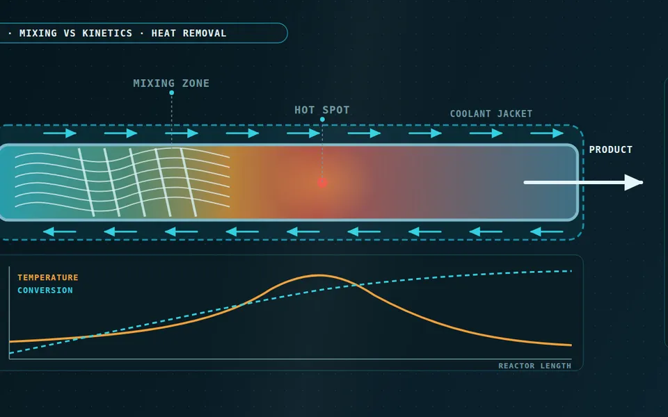
- Fire exposure. The temperature the surface sees, expressed as an adiabatic surface temperature, climbs steeply and then levels off while the fire burns. It comes from the CFD fire field, surface by surface, and not from one gas temperature for the whole area.
- Bare steel. The steel lags the exposure because it has to be heated. A thin section with a large heated surface per unit volume follows the exposure closely, a thick section lags further, and its temperature meets the critical line first.
- Protected steel. Fireproofing lowers the rate of heating, so the same member reaches the critical line later. The thermal model carries the protection layer through its thickness with temperature-dependent properties.
- Critical temperature. The temperature at which the member can no longer carry its load in the fire. It is not one number: it falls as the load carried in the fire rises, so each member gets its own line.
- Time to failure against response time. Compare the time each member reaches its critical temperature with the time your isolation, depressurising and emergency response need. A member that fails inside that window needs protection or a different layout.
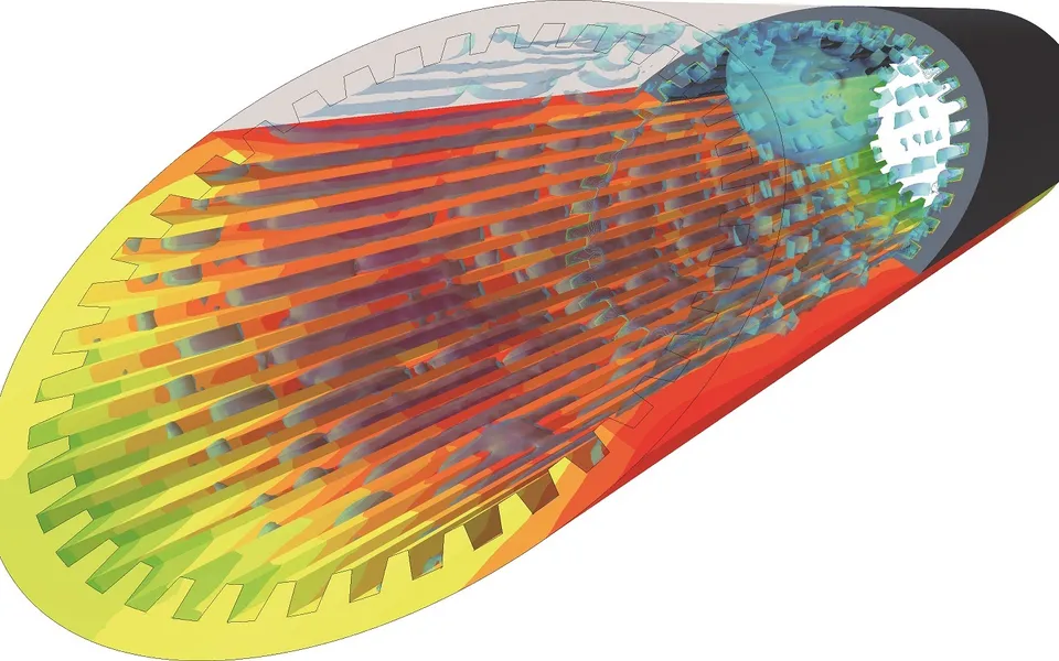
- The coupling chain. A CFD fire field gives the incident radiation and gas temperature at the surfaces. They become an adiabatic surface temperature, which drives a thermal FEA through the wall or protection layer, and the resulting temperatures go to a structural FEA that applies the real loads at temperature.
A time to failure is not a rating
Where does AI help structural fire analysis, and where does it not?
- Scenario screening. A planned set of fire runs varies leak position, direction, rate, duration, wind and protection thickness. A surrogate trained on them ranks every member by time to failure across the scenario space, so full CFD and FEA runs go to the members and fires that decide the design. See surrogate models for CFD and FEA.
- A flame-hit classifier. Whether a flame engulfs or misses a member changes its heating abruptly. A classifier on that mode sends cases near the boundary to the full model.
- Run triage. Heat-balance, mapping and convergence checks run automatically, and a run that fails never enters the training set.
It does not replace the fire physics. A surrogate cannot predict a fire unlike those it was trained on, inherits every error of the CFD model, and never decides whether a time to failure is acceptable. Each has a stated range, and outside it the request goes to the full chain. See AI surrogate models you can sign off.
From one fire study to a screening capability you keep
The return comes when your engineers can put the next layout, leak case or fireproofing option through the same chain without rebuilding the model or the checks.
- Physics model. CFD and FEA set up once, as templates: geometry clean-up, mesh, solver settings and post-processing that every later run reuses.
- Validation. Mesh and time-step studies, and comparison with tests or full-scale data, so the model's uncertainty is known before it is trusted.
- Automated runs. Scripted runs over the parameters and operating conditions that matter, on your hardware or in the cloud.
- AI surrogate. A machine-learning model trained on those runs answers in seconds and says how sure it is; low-confidence questions go back to the solver.
- Decision tool. Optimisation, trade-off charts or operating guidance, in a form your engineers and operators use every day.
- Field data. Test, trial and monitoring data flow back to recalibrate the model, so it improves with every project instead of being rebuilt.
- A scenario file holding leak position, direction, rate, duration, wind and protection specification, so a fire case is a line of input, not a new model.
- A fire-field template in your existing CFD solver, with its checks built in and a script that writes the surface exposure for every member.
- A thermal-structural template in your existing FE solver that reads that exposure, applies member loads at temperature and reports the time to failure.
- A validation record against your last fire test or instrumented incident: measures, tolerances set before the run, and results.
- A surrogate with a stated range and a gate at the flame-hit boundary, so a request outside the range goes to the full chain.
- Handover and training, so your team extends it itself. See our training and software development services.
Questions engineers ask about structural fire analysis
How long can unprotected steel last in a fire?
What is the difference between a pool fire and a jet fire for structures?
Is the ISO 834 standard fire curve valid for hydrocarbon fires?
Can simulation replace fire testing or a passive fire protection rating?
If a fireproofing decision or a fire case is waiting on a time to failure, send us the layout or model of the area, the fire scenarios from your hazard study, the member list with loads and the protection specification. We reply with how we would set up the fire exposure, which members the screening should rank first, and what the validation record should hold. Start with a conversation.