Thermal management simulation for EV batteries and e-motors
Cell heat generation, cooling plates, motor losses and the system model that ties them together: how CFD and thermal simulation keep electric drivetrains inside their temperature window.
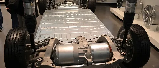
Electric drivetrains are efficient, but the heat they do produce arrives in awkward places and has to leave through tight packaging. Thermal management simulation is how that heat is followed from where it is generated to where the cooling system carries it away.
Lithium-ion cells perform best and age slowest in a fairly narrow temperature band, and cell-to-cell temperature differences across a pack matter almost as much as the average. E-motors are limited by winding insulation and magnet temperatures. Both share coolant, pumps and radiators with the cabin and power electronics, which is why their thermal design is a system problem.
Where the heat comes from
Good simulation starts with good heat sources. Errors here propagate through every later result.
- Battery cells: irreversible (resistive) heat and reversible (entropic) heat, both depending on current, state of charge and temperature.
- Busbars and connections: Joule heating that is easy to overlook and concentrates at joints.
- E-motor: copper losses in the windings, iron losses in the laminations, and magnet losses, which vary strongly with speed and torque.
- Inverter: switching and conduction losses in the power modules.
For motors, losses usually come from an electromagnetic simulation across the operating map and are mapped onto the thermal model, so the cooling is sized for the drive cycle rather than a single point.
Modelling the battery pack
Pack models range from detailed conjugate heat transfer (CHT) CFD of a module and its cold plate to fast lumped models of every cell. Both have a place.
| Model | Resolves | Best for |
|---|---|---|
| 3D conjugate heat transfer CFD | Coolant flow, cold-plate channels, conduction through cells and interfaces | Cold-plate design, flow distribution, hot-spot location |
| 3D thermal with simplified flow | Conduction in cells and structure, convection as boundary conditions | Module layout, thermal interface materials, fast iterations |
| 1D or lumped system model | Cell, coolant loop and component temperatures over a drive cycle | Pump and radiator sizing, control strategy, fast charging scenarios |
Contact resistance is a design variable
Modelling the e-motor
Motor thermal models must resolve heat paths through the windings, slot liners, stator laminations and housing to the coolant jacket or oil spray. Oil-cooled motors add two-phase and free-surface flow that needs dedicated CFD, while water-jacket designs are often well served by CHT on the jacket and a lumped network inside the stator.
From components to the vehicle system
Component models answer where the hot spots are; a system model answers whether the vehicle can hold its temperatures through a realistic day: a fast charge in summer, a mountain climb, a cold start. Reduced-order models extracted from the detailed CFD let the system model run whole drive cycles while keeping the accuracy of the 3D results.
- Run detailed CHT on the critical components to find hot spots and calibrate heat-transfer behaviour.
- Reduce each component to a fast model that reproduces those results.
- Assemble the coolant loops, heat exchangers and controls in a system model.
- Simulate drive and charging cycles, then return to 3D for any component that runs out of margin.
This loop is at the heart of vehicle thermal management simulation, and it connects naturally to heat exchanger design and to cabin thermal comfort.
Safety: thermal runaway and propagation
Beyond normal operation, packs must be designed so that a failing cell does not lead to a fire in the whole pack. Regulations such as UNECE vehicle regulations address battery safety, and simulation helps evaluate barrier materials, venting paths and cell spacing before abuse testing.
What a good thermal study delivers
- Peak and minimum cell temperatures, and the spread across the pack, through the worst realistic cycles.
- Winding and magnet temperatures over the motor's operating map.
- Pressure drop and flow split through every coolant branch.
- Sensitivity to the uncertain inputs, so margins are known rather than assumed.
Our thermal analysis team combines CFD, conduction and system models for automotive and energy clients; get in touch if your pack or motor needs its cooling proven before hardware exists.