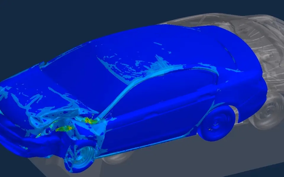
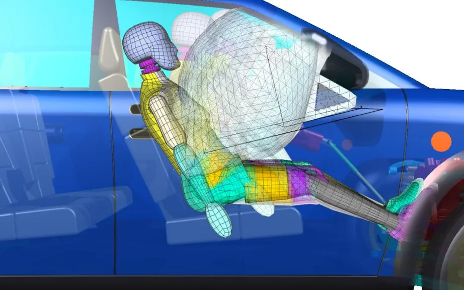
Blast protection simulation for vehicle occupants, shelters and explosives storage
A blast load reaches an occupant through a chain: hull, floor, seat, restraint, dummy. A model built to the open test methodology and checked channel by channel shows which mitigation earns its place before the trial, and the same discipline carries to walls, shelters and storage siting.
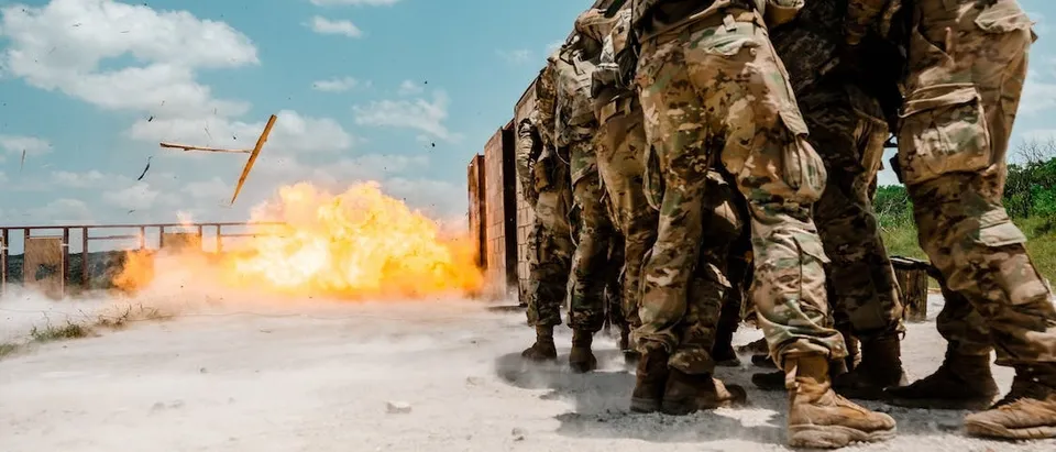
Blast protection simulation predicts how a blast load passes through a vehicle floor, a seat, a protective wall or a storage barricade into the people and equipment behind it, so you can rank mitigation options before the physical trial. We build that model, and the automated workflow around it, on your existing explicit solver.
The decision is a trade between two or three options: a seat hung from the roof or fixed to the floor, a footrest clear of the floor plate or bolted to it, a crush layer that costs floor height. A qualification trial uses up a vehicle and a place on the range, so what enters it should be the best you can find by analysis. The same question comes from the other side of the fence: an explosives store whose separation distance depends on a barricade the safety officer must justify to the authority.
What does blast protection simulation have to predict?
Three things, in order: how the structure deforms and moves, what the occupant receives through floor, seat and restraint, and whether the evidence is in a form the authority accepts. The NATO RTO report TR-HFM-090 (April 2007), “Test Methodology for Protection of Vehicle Occupants against Anti-Vehicular Landmine Effects”, separates an under-vehicle blast into local, global, drop-down and subsequent effects. The bottom plate bends within about 5 ms, the whole vehicle moves after 10 to 20 ms and peaks after 100 to 300 ms, and all is usually at rest within a second.
Momentum links the phases: the impulse on the underside sets the vertical velocity, Δv = (1/m) ∫F dt, and the vehicle falls back. The landing is a second load, and the report warns that a seat damaged in the first phase may not protect in the second.
Why is occupant blast loading hard to model?
The body is loaded through a chain. Feet on or near the floor plate are accelerated first and severely, and the pelvis follows through the legs or the seat: about 10 ms after the load for a floor-mounted seat, 15 to 30 ms for a side or roof mount, usually less severe. The pelvis load compresses the lumbar spine, and head contact with a stiff roof gives neck loads the report calls life-threatening.
The spine is judged by a model, not by peak acceleration. The Dynamic Response Index treats it as a mass on a spring and damper driven by pelvis acceleration a(t): d²δ/dt² + 2ζωn dδ/dt + ωn²δ = a(t), and DRIz = ωn²δmax/g, with ζ = 0.224 and ωn = 52.9 rad/s. Its natural period is about 120 ms, so a short pulse registers mostly as a velocity change. Mitigation has two routes: cut that velocity change by absorbing energy in hull and floor before the seat, or stretch the transfer over tens of milliseconds with seat stroke.
Where do blast protection models usually break?
Most programmes start from a floor panel under a pressure history and a dummy on a seat. It breaks in four places, and we check them first.
- Load. We take the load case from your programme or test authority. A fixed pressure history ignores that a plate moving away from the wave takes less load, so we choose between it and a coupled air-structure input per question.
- Contact and posture. Foot, boot, footrest and seat need measured stiffness and friction. The report specifies the Hybrid III 50th percentile male, its seating posture and instrumented tibias, and a dummy that sits differently reads differently.
- Seat stroke. An absorber that reaches the end of its stroke hands the pelvis a second, sharper pulse. The model carries the force-displacement curve from your component test, and the landing is run from the damaged state.
- Time step. Plate dynamics in milliseconds need small elements, and mass scaling adds mass in the floor, where the pulse is made. We check added mass and hourglass and contact energy.
These are the checks from our article on a crash model you can trust, applied to blast loading. See also our blast, explosion and fire hub and its defense and military page.
- Load case and hull bottom. Your programme or test authority defines the load. The hull bottom bulges first, shown dashed.
- Crush layer and floor plate. A deforming layer absorbs energy before the floor. Weld and stiffener failure can change how much passes.
- Seat mount and absorber. TR-HFM-090 reports pelvis load at about 10 ms for a floor mount and 15 to 30 ms for a side or roof mount.
- Decoupled footrest. Feet near the floor plate are loaded first. A footrest hung from the bulkhead keeps plate motion out of the tibia.
- Dummy channels. Tibia force, pelvis acceleration, neck load and chest pressure, read as the protocol states. Pelvis acceleration drives DRIz.
- Three phases. Local plate response, global vehicle motion, then the landing, each with its own time step and often its own method.
How do you validate the model against the test?
Validation is a record, not a plot. The report lists the channels: lower tibia axial force, pelvis vertical acceleration, upper neck forces and moment, and reflected overpressure at the chest. Its Annex I filters them to SAE J211/1 channel classes, CFC 1000 for pelvis acceleration and CFC 600 for tibia force. Our post-processing applies the same filters, and each comparison has a tolerance before the run and a result after it.
Build it from the bottom up. A floor panel, a seat on a rig and a leg impactor cost less than a vehicle, and rigs reproduce loading and interior measures in a controlled way, as Müller, Dierkes and Hampel describe. Then state the spread: run the model across posture, friction, weld strength and absorber characteristic, and report a range for each channel, not one curve.
An injury criterion belongs to its dummy and its test
What changes for blast walls, shelters and explosives storage?
The question becomes distance and shielding. The Defense Explosives Safety Regulation (DESR) 6055.09, Edition 1, Change 1 (February 2024) says damage and injury potential is normally set by three things: the separation distance, the ability of the store to suppress blast overpressure and fragments, and the ability of the exposed building to resist. The distance follows the effect that needs the most, and many distances are a constant times the cube root of the net explosive weight, D = K·W1/3.
A barricade interrupts the direct line of sight of the shock wave and can reduce load on parts of an exposed building, but it gives no protection against high-angle fragments. Protective construction may allow a reduced distance, and the rationale and supporting data go to the authority with the site plan. Where distances cannot be met, risk-based siting is allowed, and an equivalent analysis tool must document its data sources and provide verification, validation and peer-review results. We build the workflow so those records exist from the first run. The regulation is American; your authority may apply another.
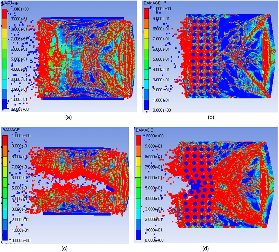
A coupled air-structure model shows where the shock reflects, diffracts over a crest and leaves a shadow, and how a wall and its anchorage respond. We take the load case from your hazard study.
- Store. Its quantity and construction set what leaves it, one of three levers the regulation names.
- Shock wave. Load falls with distance. Many DESR distances scale with the cube root of net explosive weight.
- Barricade. It breaks the direct line of sight and can reduce shock load on parts of the exposed building.
- Low-angle fragments. A barricade high and thick enough stops them. If it fails, its own debris joins the hazard analysis.
- High-angle path. A barricade gives no protection here, so the analysis does not credit it for this path.
- Exposed building and evidence. Its resistance is the third lever. A reduced distance needs rationale and data sent to the authority.
| Decision | What the model must resolve | Evidence in the record |
|---|---|---|
| Which floor or hull option enters the trial | Plate bending, crush layer, welds, local against global effects | Deformation from your test; energy and added-mass checks |
| Which seat and footrest | Mounting, absorber stroke, footrest decoupling, roof clearance | Tibia, pelvis and neck channels filtered as the protocol states |
| Margin against the injury criteria | DRIz, tibia force, neck load, chest pressure | The protocol's channels, with spread from unmeasured inputs |
| Wall or shelter layout | Reflection, diffraction, wall and anchorage response | Pressure and damage observations from your test |
| Reduced separation for a store | Barricade shadow, store construction, exposed building | The rationale and data your authority asks for |
Where does blast protection simulation stop?
Simulation supports design decisions and test planning. It does not replace the qualification trial, the explosives-safety review or the sign-off a regulation or authority requires, and nothing we build certifies, rates or approves a vehicle, shelter or store, or guarantees that a structure or an occupant survives. Whether virtual evidence counts is agreed with the programme or the explosives-safety authority before the work starts.
Where does machine learning help, and where does it not?
- Surrogate-assisted screening. The variables are seat mounting, absorber force and stroke, footrest stiffness, floor and crush-layer gauge, and for walls height and thickness. The responses are the dummy channels, DRIz and plate deformation. Planned explicit runs in LS-DYNA, Ansys Autodyn or Abaqus train a surrogate per response, and every shortlisted option is confirmed in the full model. See surrogate models for CFD and FEA.
- Mode classifier and run triage. A classifier on the mode, absorber bottoms out or not, weld tears or not, steers new runs and gates the surrogate. A failed run never enters the training set.
It does not replace the physics at the step. A surrogate trained on seats that never bottom out says nothing about one that does, and it inherits every error in the base model. It has a stated range, and outside it the request goes to the full model. See AI surrogate models you can sign off.
From one protection study to a capability you keep
The return comes when your own engineers can put the next seat, floor layer or barricade through the same checks without rebuilding the model.
- Physics model. CFD and FEA set up once, as templates: geometry clean-up, mesh, solver settings and post-processing that every later run reuses.
- Validation. Mesh and time-step studies, and comparison with tests or full-scale data, so the model's uncertainty is known before it is trusted.
- Automated runs. Scripted runs over the parameters and operating conditions that matter, on your hardware or in the cloud.
- AI surrogate. A machine-learning model trained on those runs answers in seconds and says how sure it is; low-confidence questions go back to the solver.
- Decision tool. Optimisation, trade-off charts or operating guidance, in a form your engineers and operators use every day.
- Field data. Test, trial and monitoring data flow back to recalibrate the model, so it improves with every project instead of being rebuilt.
- A parameterised floor, seat and dummy model in your existing explicit solver, with load case, mounting and absorber held in a load-case file.
- A post-processing script that reports DRIz, tibia force, neck load and pelvis acceleration with the protocol's filters, plus the energy checks, on every run.
- A validation record against your rig and trial data: tolerances before the run, results after it, and the spread from unmeasured inputs.
- An automated run set that plans the experiments, submits to your cluster and rejects runs that fail the checks.
- A surrogate with a stated range and a gate at the step.
- Handover and training, so your team extends it itself. See our training and software development services.
Questions engineers ask about blast protection simulation
What injury criteria does the NATO test methodology propose?
Is a roof-mounted seat always better than a floor mount?
Can a barricade reduce the separation distance for storage?
Can simulation replace the qualification trial?
If a seat, floor or barricade decision is waiting on a trial, send us your model or a description, your solver, the load case your programme or authority defines and the channels your last trial reported. We will reply with how we would set up the checks, which channels and tolerances the validation record should hold, and where a surrogate's range would end. Start with a conversation.