Additive manufacturing simulation: predict metal distortion and residual stress before the build fails
A metal part that warps, cracks or hits the recoater costs hours of machine time and expensive powder. How layer-by-layer residual stress works, how inherent-strain and thermo-mechanical models predict it, and how calibration and AI/ML make orientation, supports and compensation repeatable.
Additive manufacturing simulation predicts, before the build starts, how a metal part will distort under the residual stress that layer-by-layer melting locks in, and which orientation, supports, scan strategy and geometry offset will prevent it. For laser powder bed fusion (LPBF) that prediction decides whether a part is right first time or scrap after hours of machine time and costly powder.
The failures are familiar. A part curls off its supports, an overhang rises into the recoater blade and stops the build, a thin section cracks, or the part springs out of tolerance when it is cut from the build plate. Trial and error, one test build per change of orientation, supports or compensation, is slow and repeats the cost it was meant to avoid. Simulation moves those trials onto a computer, provided it is calibrated and validated for your machine and powder. We use the vocabulary of ISO/ASTM 52900:2021.
Why do metal AM parts warp, crack or hit the recoater?
Each layer is melted by a small, intense, moving heat source, then cools quickly while the material below stays much cooler. Heat leaves mainly by conduction down through the part, supports and plate, so a steep temperature gradient travels up the part with every layer.
That gradient creates the residual stress. Newly melted metal wants to shrink as it cools, but the colder, stiffer metal beneath holds it back. Where the restrained stress exceeds the yield strength, which falls steeply with temperature, the metal flows plastically. Write the strain as ε = εe + εth + εp (elastic, thermal, plastic): the first two recover on cooling, the plastic part does not. It is the permanent record of the build and leaves a self-balanced stress field, usually tension in the upper layers and near surfaces, compression elsewhere. Temperature-dependent yield strength, expansion and conductivity, and in Ti6Al4V phase changes, all enter that history.
- Layer heating. A laser or electron beam melts a thin layer; the melt pool is small, intense and moving, and each new layer reheats the ones below it.
- Thermal gradient. Heat leaves mainly by conduction down through the solid part, supports and plate, so a steep gradient moves up the part with every layer.
- Constrained contraction. The fresh layer wants to shrink as it cools but the cooler metal below holds it back. Where the restrained stress passes the temperature-dependent yield strength the metal flows, and that plastic strain does not recover.
- Residual stress locked in. The unrecovered strain leaves a self-balanced stress field: usually tension in the upper layers and near surfaces, compression elsewhere. The inherent-strain method stores exactly this strain.
- Supports and plate restraint. Supports, bolts and the stiff plate hold the part in shape and conduct heat. The restraint keeps the stress in balance, so nothing moves until it is released.
- Release and distortion. Cutting supports or removing the part from the plate removes the restraint. The stress rebalances and the part bends: overhangs and thin arms curl most.
While the part is bolted to the plate and held by supports, the stress stays in balance. The damage shows up in three places. During the build, upward distortion can reach the recoater, and crack-prone alloys can crack. At release, cutting supports or removing the plate lets the stress rebalance and the part moves. In service, residual tensile stress acts as a mean stress and can shorten fatigue life.
Part-scale or melt-pool-scale: which additive manufacturing simulation do you need?
The physics spans microns and microseconds at the melt pool and metres over many hours at the part. No single model resolves both, so practice splits the problem into levels.
| Level | Resolves | Answers | Limit |
|---|---|---|---|
| Melt pool | Melt flow, solidification | Porosity risk, process-window limits | Far too costly for a whole part |
| Track and hatch | A few tracks and layers, thermo-mechanical | Thermal history and inherent strain for a material and scan strategy | Small volumes |
| Part, thermo-mechanical | Transient heat flow and elastic–plastic response, layers lumped | Thermal history, overheating, stress, distortion | Costly; lumping trades fidelity for run time |
| Part, inherent strain | Layer-wise strain applied to a linear elastic model | Distortion, stress, support and compensation choices | Needs calibrated strains; no thermal history |
Inherent strain or thermo-mechanical simulation: which is faster, which is more faithful?
The inherent-strain method is the faster one, and the thermo-mechanical method is the more faithful one. Inherent strain applies a strain field representing the permanent strain left by the process, layer by layer, to a linear elastic model, which avoids coupled nonlinear calculations. The strain must first come from experiments or a smaller detailed model, and the method produces no thermal data, so it cannot predict overheating. A thermo-mechanical simulation couples heat transfer with elastic–plastic mechanics and follows the thermal history, at a much higher computing cost (Miki (2022) describes the trade-off).
We use inherent strain for the many what-ifs, and thermo-mechanical or small-scale models to derive strains for a new material and to check a risky region such as a downward-facing surface.
How do orientation, supports and scan strategy change distortion?
- Build orientation sets the layer count, how much of the part is overhang and how thin walls meet the recoater.
- Supports hold and restrain the part and conduct heat away. More restraint reduces distortion during the build, but stores stress that is released at removal, and costs powder and finishing time.
- Scan strategy (vector length, rotation between layers, island layout) changes the inherent strain, so a strain set is valid only for the strategy it was calibrated with.
- Pre-compensation offsets the geometry opposite to the predicted distortion. In the Giubilini, Calignano, Galati and Minetola, Politecnico di Torino (2025) study of Ti6Al4V, a calibrated simulation tool predicted distortion closely enough to apply pre-compensation, and the authors report that it reduced the measured deformation.
- Post-processing belongs in the model: stress-relief heat treatment on the plate, plate removal and support removal each change the boundary conditions. The relaxation physics is that of post-weld heat treatment; see our pages on welding stress relief and stress-relief heat treatment.
What counts as failure?
- Distortion against tolerance, and against recoater clearance during the build.
- Cracking indicators: residual stress and plastic strain against temperature-dependent strength. No universal cracking criterion exists, so we use these as a ranking calibrated against builds that cracked.
- Fatigue: tensile residual stress near surfaces lowers fatigue strength, so stress-relief and machining choices feed life prediction. See our durability and fatigue and thermal stress pages.
Calibration belongs to one machine, powder and parameter set
Pre-compensation: print the part that distorts into the right shape
Pre-compensation closes the loop between prediction and the printed part. Predict the distortion, offset the geometry the opposite way, print, scan and compare with the nominal shape. Outside tolerance, refit the strains to the difference and go round again; inside, freeze the setup as a template for that machine, powder lot and material.
- Predict. Run the calibrated process model for the chosen orientation and supports to get the distortion field of the as-built, released part.
- Invert. Offset the nominal geometry by the opposite of the predicted displacement, so the part is designed to distort into the right shape.
- Re-print. Build the compensated geometry with the same machine, powder and parameter set the model was calibrated for.
- Scan. Measure the printed part with a 3D scan and compare it with the nominal CAD, after aligning the datums carefully so alignment error is not read as distortion.
- Recalibrate. If the part is outside tolerance, fit the inherent strains to the difference between the scan and the prediction, then predict again.
- Tolerance gate and template. Inside tolerance, freeze orientation, supports, scan vectors, strain set and offset as a build template tied to that machine, powder lot and material.
Public data lets you test the workflow before trusting it on your parts. NIST AM-Bench is a continuing series of benchmark measurements and challenge problems with archived data, and its 2022 edition lists residual strains and part deflection among its measurements. Benchmark data checks the method; only your own machine's scans calibrate it.
Topology optimisation for additive manufacturing: self-supporting, low-stress shapes
An unconstrained topology optimisation is often unprintable. Three kinds of constraint fix that.
- Overhang angle. Surfaces steeper than a threshold angle need support; the threshold depends on process and material.
- Self-supporting shape with a thermal constraint. Miki (2022) notes that an overhang-angle constraint alone can leave downward-convex shapes that block heat flow and overheat. The paper adds a thermal constraint and an inherent-strain distortion constraint; its 3D examples show less distortion and overheating than the unconstrained shape.
- Residual-stress constraint. Xu, Liu and Ma (Computer Methods in Applied Mechanics and Engineering, 2022) add one to self-supporting topology optimisation for metal AM, and Shuzhi Xu's 2024 University of Alberta thesis adds support structure, scan-path optimisation and a faster LPBF process-simulation solver validated against commercial software.
Supports can be optimised too: Zhidong Zhang's 2019 University of Waterloo thesis couples a heat-transfer model with inherent-strain topology optimisation of supports, and reports lower deformation and less support material than commercial supports in its experiments.
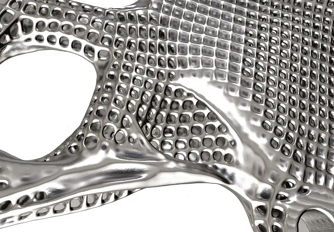
Treat these constraints as design-stage filters: they use simplified process models, so the design still goes through a calibrated process simulation before the build. See our pages on generative design and lattice structures, generative design and optimisation and turbomachinery generative design.
Where does AI/ML help additive manufacturing simulation, and where does it not?
AI/ML earns its place around the physics model, not instead of it. Each use comes with the limit we state when we build it.
| Use | What it does | Limit |
|---|---|---|
| Calibrating inherent strain from coupons | Fits the strain components so the model reproduces measured distortion of small coupons or cantilevers | Valid for the machine, powder, parameters and scan strategy tested; unlike geometry extrapolates poorly |
| Surrogates over orientation, supports, scan parameters | Trained on a planned set of process simulations; ranks many options in seconds | Trusted only inside the sampled design space; the solver does the final check |
| Closed loop from scans | Compares the scan with the predicted shape and updates strains and offset | Alignment and datum errors can look like distortion; needs a stable process |
| In-situ monitoring as inputs | Layer images or melt-pool signals flag local overheating and recoating problems | Signals show thermal anomalies, not stress; mapping to strain must be validated on your machine |
| Build-preparation templates | Scripts set up orientation candidates, support rules, the compensation run and the report | Encode today's validated rules; revisit when machine, powder or alloy changes |
The usual discipline applies: honest bounds on the design space, held-out validation and a route back to the solver. See our article on surrogate models for CFD and FEA and our pages on surrogate modelling, hybrid physics and AI modelling and validation and benchmarking.
From one distorted build to a workflow you keep
A single study answers the part it was run for. The larger return comes when calibration, build-preparation rules and the compensation loop become something your own engineers run for every new part, so the next orientation, support layout or alloy costs hours instead of a test build. That is how we build additive manufacturing simulation work.
- Physics model. CFD and FEA set up once, as templates: geometry clean-up, mesh, solver settings and post-processing that every later run reuses.
- Validation. Mesh and time-step studies, and comparison with tests or full-scale data, so the model's uncertainty is known before it is trusted.
- Automated runs. Scripted runs over the parameters and operating conditions that matter, on your hardware or in the cloud.
- AI surrogate. A machine-learning model trained on those runs answers in seconds and says how sure it is; low-confidence questions go back to the solver.
- Decision tool. Optimisation, trade-off charts or operating guidance, in a form your engineers and operators use every day.
- Field data. Test, trial and monitoring data flow back to recalibrate the model, so it improves with every project instead of being rebuilt.
- Templates for orientation, support rules and the process steps (build, cooling, stress relief, plate removal, support removal), with reports that read the same for every part.
- A validation record tying the inherent strains to your own coupons and scans, checked against public data such as NIST AM-Bench, with the deviation stated per alloy and machine.
- Automated runs over orientation, support and scan options, on your hardware or in the cloud.
- A trained surrogate that ranks options in seconds, with its range of validity written down and a route back to the solver when a part falls outside it.
- A recalibration routine: scan each build, compare it with the prediction, refit the strains when machine, powder lot or parameters change.
- Training and handover, so your engineers can extend the workflow themselves. See our training and software development services.
Questions engineers ask about LPBF distortion simulation
How accurate is LPBF distortion simulation?
Can simulation predict cracking?
Do we still need test builds?
Which software do you use?
Is this only for powder bed fusion?
If a distorted, cracked or out-of-tolerance build is on your desk, send us the geometry (STEP or STL), alloy, machine and parameter set, orientation and supports, tolerances and, most usefully, a scan of the failed build. You get a written diagnosis of the mechanism at work, the simulation level it needs and a plan for the workflow. Our additive manufacturing simulation work sits beside our consulting service, and the place to start is a conversation. For the powder bed side, see our powder bed fusion page.