Woven composite simulation from yarn unit cell and draping to part stiffness
The preform wrinkles on the diagonal, the stress model assumes 0/90 everywhere, and the 3D weave coupons do not say what the part will deliver. Unit cells, draping shear maps and a tested hand-over show which weave or angle is responsible.
Woven composite simulation predicts what a weave delivers, stiffness, damage onset and interlaminar behaviour, from a yarn-level unit cell, and what draping does to fibre angle in the real part. We build both as one chain around your existing solver, with a validation record and a surrogate of stated range, so more weave, layup and tooling questions are answered before the next coupon campaign or tool trial.
The preform drapes cleanly at the edges and wrinkles on the 45-degree diagonal, while the stress model has warp at 0 and weft at 90 degrees everywhere. The coupons came from a flat panel. Qian and colleagues report that woven prepreg formability is dominated by intraply shear and interply friction, which change fibre orientation. For a 3D weave, Friemann and colleagues note that test campaigns can be prohibitively expensive. Waiting on it: the allowables plan, preform trials, scrap, the weight target and approval dates.
What does woven composite simulation have to predict?
Three results at three scales. The unit cell, a yarn-level model of one repeat of the weave, gives stiffness and, with the right physics, damage onset. The draping model gives each point of the preform its warp and weft directions, the angle between them and the thickness. The structural model receives both; see also our article on choosing the modelling scale.
How does a yarn unit cell give stiffness, and where does it go wrong?
Mesh one repeat of the weave, tie opposite faces with periodic boundary conditions, and run six unit-strain cases, three tensions and three shears; averaged stress over strain fills the stiffness matrix, as Friemann and colleagues do. Each yarn is a transversely isotropic continuum along its path, with properties from fibre and matrix micromechanics, as in Feng and colleagues. Four choices decide the answer.
- Crimp. A loaded wavy yarn tries to straighten, pressing on the yarns it wraps and lowering in-plane stiffness. Feng and colleagues attribute plain weave's inferior moduli to its maximum number of undulations; of 9,000 random single-material 6-by-6 patterns, 28.7% beat it in both tensile moduli.
- Geometry. Friemann and colleagues call purely geometric generators far too idealised for as-manufactured material and weaving-process models costly per cell; a cell from an X-ray scan carries the real yarn paths. We use idealised cells for sweeps, scanned ones for validation and scatter.
- Nesting. A periodic cell knows nothing of neighbouring layers. Jackson and Portanova describe 2D layers as expected to nest snugly; how they nest sets thickness, fibre content and resin-rich pockets, so we model the stack.
- Mesh. Voxel meshes from scans automate the work, but Friemann and colleagues note artificial stress concentrations that can erroneously initiate damage; a conformal mesh needs every yarn separated first.
- Crimp is what makes a weave a weave. The warp yarn passes over one weft yarn and under the next, so its path undulates. Loaded along its length it tries to straighten toward the dashed line. That presses it onto the weft yarns it wraps, the amber arrows, loads the matrix through the thickness and lowers the in-plane stiffness. The cell has to carry that path, not a straight fibre.
- The pattern sets how often a yarn undulates. A plain weave interlaces at every crossing, a satin once in several. The yarn profile under each grid shows many waves against few, which is why two weaves of the same yarn and resin differ in stiffness. The pattern is a design variable, so it is a parameter of the cell.
- A cell is one repeat with matched faces. The dashed box is one repeat of the weave. Periodic boundary conditions tie the pulsing points on opposite faces so the cell behaves like a piece of infinite fabric. Three tensions and three shears applied in turn give the full stiffness matrix, and the faces must match in geometry as well as in displacement.
- Layers nest, and nesting changes the stack. A cell with periodic faces knows nothing of the layers around it. Neighbouring layers can sit in phase, or nest into each other, and the picture alternates between the two. Thickness, fibre volume fraction and the resin-rich pockets between layers all change, so the stack is modelled, not one layer.
- The mesh decides what the yarn surface does to stress. A cell built from a scan can be meshed as voxels, the right half, which automates the work but leaves a staircase. The amber spots are re-entrant corners where artificial stress concentrations can start damage the real yarn does not have. A conformal mesh, the left half, follows the surface but needs each yarn separated first.
- Stiffness arrives with a spread, and a test to meet. Each unit cell gives one point per stiffness component, the cyan dots, and cells differ because real yarn paths differ. The amber dot is the coupon measurement the band has to be checked against. The structural model receives the band and its range of validity, not a single number.
On a 3D-woven layer-to-layer angle interlock carbon composite, six cells of 6.5 by 21.5 by 4 mm from one scan gave elastic stiffnesses within 6.5% of experiments, with very little scatter between cells; damage remains future work for the authors. That is evidence for stiffness, none for strength.
Do 3D woven composites need a different interlaminar model?
In a 3D weave the warp yarns cross several weft layers, so reinforcement sits where a laminate has only resin. In a NASA Langley curved-beam test, Jackson and Portanova found 2D materials delaminated between layers while 3D weaves failed earlier by radial cracks between surface plies, which they trace to crack formation, not low through-thickness strength. In indentation, an orthogonal interlock was among the most damage-resistant materials.
A cohesive interface tuned to a laminate's delamination toughness knows nothing of a yarn crossing the crack. We model the through-thickness yarns explicitly, or fit a bridging law to your delamination tests, and say which; see composite modelling approaches. Friemann and colleagues note that heterogeneity of tens of millimetres forces coupon methods to be adjusted so the gauge holds a representative volume; a model-to-test comparison must state how many cells it holds. Fatigue is checked separately: composites fatigue simulation.
How does draping simulation give the local shear angle, and what is locking?
Yarns are quasi-inextensible, so fabric covers a doubly curved surface by trellising: the angle between warp and weft changes by the shear angle γ and cell area falls with cos γ, raising local thickness or fibre content. Boisse and colleagues review the two tests. The picture frame is highly constrained and can pick up parasitic fibre tension; the bias-extension test avoids that but assumes no warp-weft slip. A benchmark among seven groups was needed to agree good practice, and prepreg shear is measured at forming temperature.
Locking is where yarns touch and shear stiffness climbs; wrinkles tend to start. The review warns it is not a clean limit: wrinkling involves all the stresses, and angles above 60 degrees have been measured at high binder pressure without wrinkles. Fabric bends far more easily than shell theory predicts, so draping shells decouple bending from membrane stiffness, and friction between plies of different orientation dominates: with zero interply friction, simulations showed no wrinkles. Per Qian and colleagues, kinematic models that map a flat mesh onto the surface omit material and process.
Qian and colleagues validated a finite-element model on a four-ply twill carbon prepreg double dome. In the 0/90° ply the largest shear angle, 43.7°, sat in the dome-to-flat transition. Predicted angles differed from CT-tracer measurements by less than 14.1% at four positions there and less than 19.7% at three in the ±45° plies, and a wrinkle appeared in both simulation and scan. We carry that spread forward as input uncertainty. In explicit runs we keep kinetic energy small against internal energy, so mass scaling cannot create wrinkles.
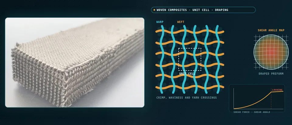
- Yarns do not stretch, so the fabric shears. To cover a doubly curved surface the fabric trellises: warp and weft stay straight and the angle between them changes by the shear angle, the amber arc. The area of each cell falls with the cosine of that angle, so the same fibre packs into less area and the local thickness or fibre content rises.
- Shear is not uniform. On a dome draped with 0/90 fabric the large angles sit on the diagonals, the amber lobes, where the surface demands the most trellising, and the centre and the axes stay low. This map is a result of the draping model, and it is the field that has to be handed on.
- Locking: stiffness climbs and wrinkles follow. As the angle grows the yarns come into contact, the in-plane shear stiffness rises steeply and wrinkles tend to start, the shaded zone. The locking angle is not a clean limit: wrinkling involves all the stresses in the fabric, so holder tension and friction can move it.
- Holder force and ply friction decide the wrinkle. Plies of different orientation slip against each other, the opposed arrows. Friction turns the slip into compression and the upper ply buckles, while holder force adds tension that can suppress it. A draping model without both inputs predicts the wrong wrinkles, so they are calibrated.
- The mapping rule is part of the model. The draping mesh is fine and the structural mesh is coarser. Each structural element receives a warp and a weft direction, a pair no longer at a right angle, drawn as the crossed marks, and how angles are averaged across the finer mesh is a modelling choice with its own error near gradients.
- Per-element input, and wrinkles flagged. Each element carries its fibre angle and local fibre content into a stiffness taken from a sheared unit cell or from tests. Where the draping model predicts a wrinkle the element is flagged, because a smooth structural mesh does not contain one.
How do draped fibre angles reach the structural model?
Per element the draping model gives two direction vectors and a thickness, not one ply angle: after shear, warp and weft are not orthogonal. The structural mesh is coarser, so the mapping rule, nearest element, area-weighted, angles or vectors interpolated, is a modelling choice with an error near gradients. Properties then come from sheared unit cells or tests as a function of shear angle and fibre content, and wrinkles are flagged, not modelled. We script it, test it on patches with known angle fields and report the stiffness difference from the nominal 0/90 model.
Which woven composite question needs which model?
| Question | Model | Reports | Limit to state |
|---|---|---|---|
| What stiffness does this weave give? | Unit cell, periodic faces, six strain cases | Stiffness by component | Yarn data, geometry, nesting |
| How scattered is the as-made material? | Several scanned or randomised cells | Spread per component | Elastic only; strength needs damage |
| Where does the preform shear and wrinkle? | Draping shell: shear, bending, friction | Shear map, wrinkle flags | Characterisation scatter |
| What does the sheared fabric do in the part? | Mapped warp and weft directions | Local stiffness by element | Mapping rule; wrinkles not modelled |
| Does a 3D weave resist delamination? | Cell with through-thickness yarns, bridging law | Crack growth resistance | Law fitted to your tests |
| Sweeps over weave, yarn size, layup | Surrogate on designed cell runs | Moduli inside the sampled range | Range only; gate to full cell |
A validated unit cell is not a design allowable
Where does AI help woven composite design, and where does it not?
- Surrogates over weave and yarn parameters. Feng and colleagues solved repeated unit cells of 9,000 random 6-by-6 patterns for in-plane E1, E2 and G12 and trained networks to predict them and propose patterns for a target modulus. Different patterns can share a modulus, so the inverse problem is many-to-one: we return candidate sets.
- Scan segmentation. Friemann and colleagues train a 3D U-net on fully synthetic labelled data; once trained, a volume becomes a finite element input file in under a minute, with unit cells still picked by hand.
- Physics-encoded surrogates. Ghane and colleagues note that data-driven surrogates for woven composites often need big data, lack interpretability and extrapolate poorly, and embed physically recurrent yarn networks in a meso-to-macro model for better generalisation under cyclic loading. We keep the constitutive law and learn only what the physics leaves open.
- Calibration. Shear, bending and friction parameters are identified against your test curves, scatter included.
AI does not repair a wrong yarn law, and a surrogate fitted to some weaves says nothing about another. Ours state their range and send other queries to the full cell. See our surrogate modelling, hybrid physics-AI, uncertainty quantification and generative design pages and articles on surrogate models and validating them.
From one unit cell to a workflow your team keeps
The return comes when your engineers run the next weave, resin or tool through the same chain.
- Physics model. CFD and FEA set up once, as templates: geometry clean-up, mesh, solver settings and post-processing that every later run reuses.
- Validation. Mesh and time-step studies, and comparison with tests or full-scale data, so the model's uncertainty is known before it is trusted.
- Automated runs. Scripted runs over the parameters and operating conditions that matter, on your hardware or in the cloud.
- AI surrogate. A machine-learning model trained on those runs answers in seconds and says how sure it is; low-confidence questions go back to the solver.
- Decision tool. Optimisation, trade-off charts or operating guidance, in a form your engineers and operators use every day.
- Field data. Test, trial and monitoring data flow back to recalibrate the model, so it improves with every project instead of being rebuilt.
- A parametric unit-cell template: pattern, yarn and spacing as parameters, six strain cases scripted, checked on a case with a known answer.
- A scan-to-cell hand-over if you hold CT data, with rejected cells recorded.
- A draping template of shear, bending and friction data, each with its test, temperature and scatter.
- A mapping tool with a contract: warp and weft vectors, shear and thickness per element in a versioned, tested file.
- A validation record: coupons, a draped trial panel measured optically or by CT, tolerances set before the run.
- A surrogate with a stated range and a gate to the full cell.
- Handover and training, so your team runs and extends it: our training and software development services.
How credible is a woven composite simulation?
Verification is convergence: mesh or voxel size and load increment in the cell, a periodic-boundary check on a known case, the draping mesh and energy balance. Validation uses data you hold or can generate: coupons, a draped panel measured for shear angle, one case held back. Uncertainty is sampled: yarn and matrix data, cell-to-cell geometry, shear and friction data. Test scatter can be large: Boisse and colleagues report a 26-laboratory compressibility benchmark of woven and non-crimp glass fabrics with coefficients of variation of maximum pressure up to 50%. The answer is a range with ranked contributors.
Questions engineers ask about woven composite simulation
What is a unit cell in woven composite simulation?
Can I use the shear locking angle as a wrinkling limit?
Does a 3D weave remove delamination?
Can simulation replace coupon or draping trials?
If a weave choice, preform trial or allowables plan is waiting on this, send us the weave style, yarn and resin data, the coupon and picture-frame or bias-extension curves you hold, a draped trial's measurements and the part geometry with layup. We reply with the unit-cell and draping chain we would set up, the validation we would run and what a surrogate could cover. Start with a conversation, or see our woven fabric composites page.