Blast resistant design procedure for buildings and process modules you can defend
From the design-accident load to the response limit and the record a reviewer can reopen: how SDOF and full finite element models, progressive collapse checks and surrogates fit into one blast resistant design procedure, and what we build around your solvers.

Blast resistant design is a chain of five decisions: which explosion the structure must withstand, what pressure-time load it puts on each surface, how the structure responds, what response is acceptable, and whether local damage stays local. We build that chain as a tested workflow around your existing explicit and CFD solvers, so every design review starts from a record you can reopen.
A new compressor module is going in beside the operator building, and the explosion study has returned its design-accident load. The building can stay, take a strengthened wall and roof, or move, each with its own cost and schedule. The study cannot choose between them. How this structure responds to that load can, and a design procedure computes, checks and records that response.
What must a blast resistant design protect, and from which explosion?
Start with people and function, not the model. The US Chemical Safety Board's trailer blast damage data from the 2005 BP Texas City refinery explosion cover some 44 trailers near the isomerisation unit. The fifteen fatalities occurred in or near two trailers 121 to 136 feet from the blowdown drum; occupants were injured as far as 479 feet away and damage reached almost 1,000 feet. Board Member John Bresland said modest overpressures that would cause no significant harm to a modern blast-resistant refinery control room can devastate a trailer. The same load is survivable in one building and not in another.
API's January 2024 editions of RP 752, RP 753 and RP 756 set out how to place permanent buildings, portable buildings and tents in process plants to minimise risk to personnel from explosion, fire and toxic release. Where a building stays in a hazardous area, blast resistant design takes over.
The design standard defines what protected means. ASCE/SEI 59, Blast Protection of Buildings, sets four levels of protection, as its chair's overview in STRUCTURE magazine describes. The goals are to limit potential structural collapse, keep the envelope intact to protect occupants and assets, and minimise flying debris, and its response limits for flexural and compression elements are calibrated to the levels. Its default procedure converts the design explosion to an equivalent quantity of TNT. A vapour cloud explosion comes from an explosion study instead, and the response steps that follow are the same.
How do you define the blast load on a building?
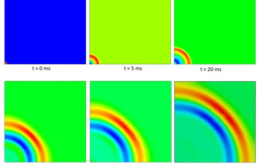
Two numbers describe the free-field pulse: peak overpressure and positive-phase impulse. For a given explosion both follow from the scaled distance Z = R/W1/3, the Hopkinson-Cranz relation, and the waveform is commonly written p(t) = pso(1 − t/t+) e−bt/t+, the Friedlander form. A building rarely sees pso. The wave reflects, so a face-on surface takes a higher reflected pressure, and the roof and sides take a pulse shaped by diffraction and clearing. ASCE/SEI 59 idealises the shock front as a triangular pulse with the same peak reflected pressure and the same impulse, then combines it with a dynamic-pressure pulse.
Simple rules stop early. EN 1991-1-7 gives an equivalent static pressure for an internal natural-gas explosion, but the JRC handbook on action effects for buildings states its validity: rooms up to 1,000 m3, with a vent-area-to-volume ratio between 0.05 and 0.15 per metre. A congested process module is outside that. There a CFD solver such as Ansys Fluent gives the pressure field on every face and we map it onto your structural model, so each element carries the computed load. Whatever its source, a load enters the procedure as a pressure-time curve per surface with a stated basis, owner and scenario number.
- Blast pressure pulse. The load on a surface rises almost instantly to a peak, decays through a positive phase and dips into a weak negative phase. The Friedlander form describes the free-field pulse; a surface sees a reflected and diffracted version of it.
- Impulse. The area under the positive phase is the impulse. For a member that responds slowly compared with the pulse, this area, not the peak, sets the response.
- Equivalent triangular pulse. Design procedures replace the curve with a triangle that has the same peak and the same impulse, so the duration is set by the impulse. The idealisation is only as good as the match between the pulse and the member.
- Equivalent single-degree-of-freedom model. A wall, slab or beam is reduced to one equivalent mass on a nonlinear spring, loaded by an equivalent force. The resistance function carries the yield and the plastic range of the member.
- Response and limit. The displacement history rises past yield, peaks and settles about a permanent set. The check is the peak against the response limit for the chosen level of protection. The ring marks the value the record must report.
- Duration against period. The pulse duration t_d compared with the natural period T of the member sets the regime. Short against T, the impulse governs; long against T, the peak pressure governs; in between, both and the pulse shape matter.
Is an SDOF model enough, or do you need full finite elements?
A single-degree-of-freedom model reduces a wall, slab or beam to one equivalent mass on a nonlinear spring: meü + R(u) = Fe(t), where R(u) is the resistance function and Fe the load transformed to the same degree of freedom. The natural period T sets the regime. If the load duration td is much shorter than T, impulse governs. If it is much longer, peak pressure does. In between, both and the pulse shape matter. A pressure-impulse diagram draws that idea once for a member, as the curve of load combinations that just reach the response limit. ASCE/SEI 59 lists pressure-impulse charts, lumped-parameter models and finite element models among its methods.
SDOF works while one mode of one member governs. It stops at openings, connections, interacting members, non-uniform load and failure modes it cannot represent, such as support shear or a frame losing a column. Then a full model in your existing explicit solver, LS-DYNA, Ansys Autodyn or Abaqus, takes over, and the SDOF model becomes its cross-check. Our blast, explosion and fire software page covers the solver landscape.
| Design question | Load input | Model | Where it stops |
|---|---|---|---|
| Does this wall or slab meet its limit? | Pulse per face: peak and impulse | SDOF with a resistance function, or a pressure-impulse chart | One dominant mode; no support shear or connection failure |
| How do frames, openings and connections share the load? | Pressure-time history per face | Multi-degree-of-freedom or finite element frame model | Mesh and material model must carry the failure modes that matter |
| What happens to a roof, cladding or window system? | Face loads with clearing; negative phase if it governs | Shell or solid elements in an explicit solver | Window systems: ASCE/SEI 59 requires dynamic analysis or full-scale dynamic testing |
| Does the module see more than the free-field load? | Geometry and explosion scenario | CFD pressure field mapped onto the structural model | Calibration and mesh dependence of the explosion model |
| Does local damage stay local? | Load case for the damaged state | Nonlinear dynamic analysis with element removal | Only as good as the removal scenarios and failure criteria |
Which response limits and damage criteria apply?
They come from the standard, the protection level and the owner, never from the model. ASCE/SEI 59 calibrates its limits to its four levels, and lets you credit the higher yield and failure stresses that very fast strain rates produce through strength increase factors. The US military criteria show why the edition matters. Change 2 of UFC 3-340-02, Structures to Resist the Effects of Accidental Explosions, revised its diagonal tension and shear requirements and made reinforcement development and lap lengths follow ACI 318. A validation record that does not name the edition has not said which limit it checked.
A passing result is evidence, not approval
How do you keep local damage from becoming progressive collapse?
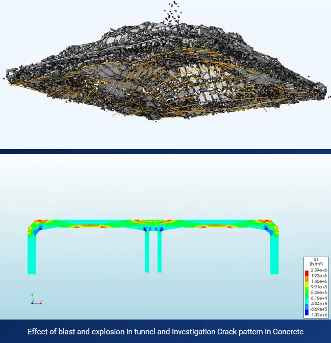
A blast can remove one column or a length of wall; the question is whether the rest stands. UFC 4-023-03, Design of Buildings to Resist Progressive Collapse (Change 4, June 2024) names three approaches: tie forces, alternate path and enhanced local resistance. Its alternate path method requires the structure to bridge over vertical load-bearing elements notionally removed one at a time, by linear static, nonlinear static or nonlinear dynamic procedures. ASCE 76-23 is a separate standard on disproportionate collapse, written to be independent of the cause of the initial damage. EN 1991-1-7 Annex A sets tie rules scaled by consequence class, as the JRC handbook summarises.
Tie rules set a minimum; they know nothing of your connections. A nonlinear dynamic model with element removal in your explicit solver tests the structure you have. UFC 4-023-03 also requires design submittals to list the design software and include the electronic input files, and an alternative rational analysis to be reviewed by an independent third-party engineer or the facility owner's authorized representative.
Where does AI help blast resistant design, and where does it not?
- A response surface over the load plane. Planned full-model runs at chosen peak pressures and impulses fit a surrogate of the limit curve for a member family. The designer reads the margin for each scenario from it and confirms the governing ones in the full model.
- A failure-mode classifier. It sorts runs into flexure, support shear, connection failure or collapse, and gates the surrogate: near a mode change, the request goes to the full model.
- Load uncertainty propagation. The spread of the explosion study goes through the surrogate, so the margin is stated against the upper tail of the load, not its mean.
- Run triage. Energy balance, contact penetration and element-removal checks run automatically, and a failed run never enters the training set.
- Two asymptotes. For a given member and limit, a very short pulse is judged on its impulse alone and a very long one on its peak pressure alone. The curve bends toward the first asymptote on the left and the second on the right.
- Response-limit curve. Every combination of peak pressure and impulse on the curve just reaches the chosen response limit. Loads above and to the right of it exceed the limit, loads below and to the left stay within it.
- Planned full-model runs. Each dot is a run of the full finite element model, placed to locate the curve: more of them where it bends, fewer on the flat branches. The surrogate and the SDOF model are both checked against these.
- Design-accident load and its spread. The explosion study gives a spread of loads, not a point. The margin is read against the upper tail of that spread, and the dots show how close it comes to the curve.
- Stricter level of protection. A higher level of protection allows less response, so its curve lies closer to the origin. The same load that is acceptable at one level can fall well outside the next.
- Failure-mode gate. Close to the impulse asymptote, support shear or a connection can govern before the flexural limit does. A surrogate trained on flexural runs hands requests in this zone to the full model.
AI does not choose the design accident, set the protection level or confirm that the load is right. A surrogate trained inside one failure mode has nothing to say about a design that changes it, and it inherits every error in the base model. It carries a stated range, and a request outside it goes to the full model. The energy-balance checks are those of our article on a crash model you can trust. See surrogate models for CFD and FEA and AI surrogate models you can sign off.
From one blast study to a design procedure your team keeps
The return comes when the next building or scenario goes through the same procedure without rebuilding the model or the record.
- Physics model. CFD and FEA set up once, as templates: geometry clean-up, mesh, solver settings and post-processing that every later run reuses.
- Validation. Mesh and time-step studies, and comparison with tests or full-scale data, so the model's uncertainty is known before it is trusted.
- Automated runs. Scripted runs over the parameters and operating conditions that matter, on your hardware or in the cloud.
- AI surrogate. A machine-learning model trained on those runs answers in seconds and says how sure it is; low-confidence questions go back to the solver.
- Decision tool. Optimisation, trade-off charts or operating guidance, in a form your engineers and operators use every day.
- Field data. Test, trial and monitoring data flow back to recalibrate the model, so it improves with every project instead of being rebuilt.
- A load-definition template per scenario: the source, the pressure-time curve for each surface, its basis and its owner, held in one file.
- A parameterised structural model in your existing explicit solver, with an SDOF cross-check script for each member family.
- A validation record naming the standard edition, protection level and response limits, with the comparison to your tests or published benchmarks, the mesh and time-step checks and the spread from unmeasured inputs.
- An automated run set that plans the pressure-impulse runs, submits them to your cluster and rejects any that fail the energy and contact checks.
- A surrogate with a stated range and a gate at the failure-mode boundary.
- Handover and training, so your engineers extend it themselves. See our training and software development services.
Questions engineers ask about blast resistant design
What is blast resistant design?
What is the difference between SDOF and finite element blast analysis?
Can simulation replace blast tests or code compliance?
What does a reviewer need to see?
What do you need from us to start?
If a building, module or structure is waiting on a blast decision, send us the explosion study or its load summary, the structural drawings or model, the protection level and standard edition you work to, and the review comment you most need to close. We reply with how we would set up the load definition and the response checks, what your validation record should hold, and where a surrogate's range would end. Start with a conversation. See also our blast, explosion and fire hub and design procedures page.