Drone aerodynamics simulation for propeller wash, ground effect and gusts
The prototype matches the thrust stand, then bounces on landing, hunts in a crosswind and misses its endurance. Simulating propeller, airframe, ground and low-Reynolds wing on your own solver finds which effect is yours before the next build.
Drone aerodynamics simulation predicts the forces on a multicopter or fixed-wing UAV where they depart from the datasheet: propeller thrust and torque in the airframe's own wash, ground effect on landing, gust response, and the drag of a wing flying at low Reynolds number. We build it around your existing solver and deliver the thrust, ground-effect and gust maps your flight-dynamics model needs, so the layout and the propeller are chosen before the next prototype and flight-test slot.
The prototype matches the thrust stand and then misbehaves in the air. It bounces on touchdown, hunts in a crosswind, or uses more battery than the wing's polar promised. The airframe freeze and the propeller order are due, the flight-test slot is booked, and every answer so far came from the previous build. A datasheet and a single polar cannot say which effect is yours.
What does drone aerodynamics simulation have to capture?
Start with the propeller. Thrust and power follow from CT = T/(ρn2D4) and CP = P/(ρn3D5) as functions of the advance ratio J = V/(nD), with n the rotation rate and D the diameter. The open UIUC propeller database holds wind-tunnel measurements of these maps for propellers used on small UAVs and model aircraft, and defines its static-test Reynolds number on the chord and speed at 75% of the blade radius. Its authors report good agreement with Ohio State measurements taken by different techniques. That is the validation target for the isolated propeller, met before an airframe is added.
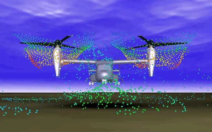
Then add what the map leaves out. In the airframe the propeller sees uneven inflow from arms, body and neighbours; in a gust it sees a different advance ratio; near the ground it breathes its own wash. A flight-dynamics model needs these as forces and moments across rotor speed, forward speed, height and wind: that envelope, not one hover case, is the brief.
How do propeller wash, airframe and ground interact?
Close to the ground, the steady one-dimensional model used by Shi and colleagues (2019), T/T∞ = 1/(1 − μ(R/4z)2), raises thrust at fixed rotor speed as the height z falls, with μ equal to 1 for one propeller and tuned for several. The same authors state that such models assume steady flow, while most real cases are unsteady. A multirotor adds the fountain and recirculation of the diagram, which no one-dimensional formula holds.
- Rotor slipstream. Each propeller accelerates air downward, and the stream contracts below the disc and carries the tip vortices with it. A propeller's thrust at a given rotor speed depends on the inflow it sees, so the thrust-stand map of the bare propeller is the starting point, not the answer.
- Arms, body and payload in the wash. The wash falls on the arms, motor pods, battery and payload and loads them downward. That is airframe loading, a separate question from rotor thrust, and it can matter even when the airframe barely changes the thrust.
- Stagnation and wall jet. The ground stops the slipstream and turns it into a jet along the surface. That changes the flow through the rotor disc, so at a given rotor speed the thrust differs from its free-air value.
- Fountain and recirculation. Wall jets from neighbouring rotors meet under the body and rise as a fountain onto the underside of the airframe, and air can curl back into a rotor inlet. These flows are unsteady, and published work notes that standard ground-effect models assume steady flow (Shi et al., 2019).
- Gust and crosswind. A gust changes the inflow speed and angle at every rotor and pushes the wakes downwind, so one rotor can sit in the wake of another or of the body. Each rotor's thrust and torque change by a different amount, and the controller sees the difference as a moment.
- Thrust against height. At a fixed rotor speed thrust rises as the vehicle nears the ground and approaches its free-air value higher up. The line is the steady one-dimensional estimate, with μ equal to 1 for one rotor and tuned for several (Shi et al.); the scatter stands for what unsteady, multi-rotor flow does around it. CFD at sampled heights fills the map a flight model needs.
How much the airframe changes the rotors depends on the flight state, which is why we simulate before simplifying. Caprace and colleagues ran a vortex particle-mesh large-eddy simulation of a generic quadcopter in forward flight at 10 m/s. The airframe changed average rear-rotor thrust by at most 2.4% and the rotors' share of aircraft lift and drag by under 2%, yet it took peak loads from the nearby blades. A simple rotor-force model can suffice for trim and not for arms, payload mount and fatigue. It is one generic geometry in one condition, not an allowance for yours.
On a fixed-wing or tilt-wing drone the propeller works on the wing. In an open study of a distributed-propeller layout, Lan and colleagues (2026) find that the slipstream raises lift and drag but lowers the lift-to-drag ratio, and that the tip vortex splits on meeting the wing and reshapes the spanwise lift.
Rotating reference frame, sliding mesh or actuator disc?
A rotating reference frame (MRF) solves one steady state with the rotor frozen: cheap, and enough for thrust and slipstream trends. Lan et al. state that it cannot capture unsteady features, that a sliding mesh costs significantly more and generally agrees more closely with experiment, and that an actuator disc rests on engineering heuristics for blade loading, so it suits conceptual design. They chose MRF because wing and aircraft lift and drag needed no more.
For a drone we choose by question. Thrust and torque maps and sweeps over many operating points run on MRF or a body-force model, checked against the measured map. Hover near the ground, a tip vortex passing an arm and a rotor in a neighbour's wake are unsteady, so they run on a sliding mesh with a time step that follows blade passage. For a ducted fan we resolve blades and duct together in hover and cruise, and use body-force sources for sweeps only where that comparison holds. Rotor noise is a separate chain from the same blade loads, covered in our eVTOL rotor-noise article.
Why does low Reynolds number break default CFD settings?
Small wings and blades fly where the boundary layer can stay laminar, separate behind the suction peak, turn turbulent in the free shear layer and reattach, enclosing a laminar separation bubble. Mishra, Kumar and De show the modelling consequence for a NACA 0021 at a Reynolds number of 120,000: Spalart-Allmaras and linear k-ω SST are fully turbulent in formulation and cannot form the bubble, so they under-predict drag at low angle of attack, while the k-kl-ω transition model and a nonlinear-corrected k-ω SST place it. Their near-wall mesh keeps y+ below 1 with no wall function, and the inflow turbulence comes from the experiment.
- Laminar layer separates. At low Reynolds number the boundary layer can stay laminar over the front of a wing or propeller blade. A laminar layer resists an adverse pressure gradient poorly, so it separates behind the suction peak.
- Transition in the shear layer. The separated layer is unstable: it rolls up into vortices and becomes turbulent in mid-air, away from the wall. A model that assumes fully turbulent flow never lets this step happen.
- Reattachment closes the bubble. If the turbulent shear layer has enough energy it returns to the surface and traps the air between separation and reattachment, with reverse flow near the wall. The bubble lowers the performance of the section and affects its stall.
- Pressure plateau. Under the bubble the surface pressure is nearly flat and then recovers at reattachment, unlike the smoother curve of attached flow. That change in the pressure distribution is how the bubble shows up in drag, lift and the efficiency of a small propeller.
- Which model can see it. Fully turbulent RANS models (Spalart-Allmaras, linear k-ω SST) cannot form the bubble; in a NACA 0021 study they under-predicted drag at low angle of attack (Mishra et al.). A transition model or a nonlinear-corrected k-ω SST can place it, and DES or LES resolve its dynamics at a far higher cost.
- Incoming turbulence. Transition and reattachment respond to the turbulence in the incoming air and to the surface finish, so a tunnel, a gusty field and a printed or moulded part do not give the same bubble. The inflow turbulence is a boundary condition to measure and carry into the model.
So we use transition-aware models on wings and blades, near-wall resolution without wall functions, and one scale-resolving case where the bubble drives the decision (endurance, propeller efficiency, stall) to calibrate the cheaper model. Tunnel turbulence and surface finish change the bubble, so a measured polar carries them. Verification is mesh and time-step refinement on the template, reported as a grid convergence index; validation is the propeller map, a thrust-against-height or thrust-in-wind test and flight logs; uncertainty is propeller tolerance, surface finish, inflow turbulence and motor-speed accuracy, swept to a range.
| Question | Model | What it reports | Decision it supports |
|---|---|---|---|
| Isolated propeller map | MRF or sliding mesh | Thrust and power coefficients against J, versus test | Propeller and motor choice |
| Hover and landing near the ground | Sliding mesh over a ground plane | Thrust and torque against height | Landing gains, ground-effect map |
| Arms, body and payload in the wash | Resolved rotors with the airframe | Download and peak loads per part | Layout, payload position, arm fatigue |
| Gust and crosswind | CFD at sampled inflow speeds and angles | Thrust, torque and moment shifts per rotor | Gain schedule, disturbance model |
| Fixed-wing endurance | Transition-aware RANS, scale-resolving check | Polars with bubble drag, slipstream effect | Wing section, cruise point |
| Ducted fan | Resolved blades and duct, then body force | Thrust, power, duct loads against inflow angle | Duct design, diameter |
Where does AI help drone aerodynamics, and where does it not?
- Thrust and torque maps. A surrogate trained on resolved runs and propeller test data returns CT and CP over rotor speed and inflow without a new solve, with its range stated.
- Residual force for flight dynamics. Shi et al. trained a network with four hidden layers on pilot-flown data between 0.05 m and 1.50 m height to learn the ground-effect force for the controller. O'Connell et al. (2022) learned wind effects from 12 minutes of flight data in six wind conditions up to 22.0 km/h and tested up to 43.6 km/h. We build the same structure, a nominal model plus a learned correction, trained on CFD sweeps over height, speed, rotor speed and inflow angle and recalibrated on your flight and tunnel logs.
- Layout screening. A surrogate over propeller pitch and diameter, arm length and payload position ranks layouts for the resolved runs, tested on held-out full runs.
It does not replace the physics. A surrogate cannot see a bubble its training runs never resolved, and a learned ground-effect or gust force belongs to the airframe and propeller it was trained on. O'Connell et al. note that CFD-derived wind models are often expensive and limited to steady wind, so we use CFD offline for the steady map and tune the unsteady part on flight data. The physics stays the evidence, and a gate sends anything outside the surrogate's range back to a full solve. See surrogate models for CFD and FEA and our reduced-order models and uncertainty quantification pages.
A simulated thrust or margin is not an airworthiness argument
From one drone study to an aerodynamic workflow you keep
The return comes when your engineers can put the next propeller, arm length or payload position through the same chain.
- Physics model. CFD and FEA set up once, as templates: geometry clean-up, mesh, solver settings and post-processing that every later run reuses.
- Validation. Mesh and time-step studies, and comparison with tests or full-scale data, so the model's uncertainty is known before it is trusted.
- Automated runs. Scripted runs over the parameters and operating conditions that matter, on your hardware or in the cloud.
- AI surrogate. A machine-learning model trained on those runs answers in seconds and says how sure it is; low-confidence questions go back to the solver.
- Decision tool. Optimisation, trade-off charts or operating guidance, in a form your engineers and operators use every day.
- Field data. Test, trial and monitoring data flow back to recalibrate the model, so it improves with every project instead of being rebuilt.
- A parametric propeller-and-airframe model in your existing solver, such as MSC Cradle, Ansys Fluent or Siemens STAR-CCM+: propeller, arm length, payload position, ground plane and wind direction as parameters, with the rotating-frame and sliding-mesh templates, transition settings and mesh controls on record.
- A run manager that sweeps rotor speed, inflow, height and wind angle and writes CT, CP, forces and moments per rotor and part.
- A validation record against propeller maps and your thrust-stand, tunnel and flight logs, with tolerances set before the run.
- A surrogate with a stated range and a gate to the full model outside it, exported as a lookup or residual-force function for your flight-dynamics simulation.
- Arm and wing loads passed to your structural model through one-way coupling.
- Handover and training, so your team runs and extends it. See our training and software development services, and the drone aerodynamics page.
Questions engineers ask about drone aerodynamics simulation
How do you simulate ground effect for a drone?
Is CFD accurate enough for small propellers at low Reynolds number?
Can CFD model gusts for flight control?
Can simulation replace wind-tunnel or flight testing for a drone?
Does the airframe change propeller thrust enough to matter?
If a propeller order, an airframe freeze or controller tuning is waiting on aerodynamic answers, send us the airframe geometry (CAD or a simplified body), the propeller and motor data with any thrust-stand curves, the heights, speeds and winds you must handle, and the flight logs or tunnel runs you have. We reply with how we would build the model, the maps it would deliver, what the validation record should contain and what a surrogate could cover. Start with a conversation, read the drone aerodynamics capability page, or see the wider aerodynamics simulation hub.