Helicopter rotor CFD for blade-vortex interaction, tail shake and rotor loads
A hub fairing or tail boom that looks right on the drawing can shake the airframe in fast forward flight, found only after the parts are built. Coupling rotor CFD to a structural and trim model on your own tools finds the wake, the loads and the airframe response first.
Helicopter rotor CFD resolves the unsteady flow around turning, flexing blades (tip vortices, blade-vortex interaction, retreating-blade stall, the wake that reaches the tail) and couples it to a structural and trim model, so airloads, blade motion and vibration agree. We build that chain around your solver and rotor code, so a blade, hub-fairing or tail-boom change is judged before parts are built or a tunnel slot is booked.
The hub fairing and tail boom are due to be frozen, and rotor and airframe have only been tested apart. Then fast forward flight shakes the airframe at one to two times the rotor frequency. A University of Stuttgart study records that several designs met this tail shake in the prototype stage and that the cure was usually a new tail boom, fairing or hub cap (Schäferlein, Keßler and Krämer, 2017).
Why is helicopter rotor CFD harder than fixed-wing CFD?
A blade section sees a speed that changes with azimuth ψ, roughly Ωr + V sinψ for rotor speed Ω, radius r and forward speed V: the advancing tip nears compressibility while the retreating side runs slow at high incidence, in dynamic stall, with reversed flow near the root. The advance ratio μ, forward over tip speed, sets that asymmetry.
The blades are elastic and the rotor is trimmed, so pitch settings must meet thrust and moment targets. NASA Langley concludes that trim depends on aerodynamic loads and structural deformation and vice versa, so a complete simulation needs coupled aerodynamics, structures and trim.
- Tip vortex. Every blade sheds a concentrated vortex from its tip, a thin tube of rotating air whose strength follows the blade loading. It does not stay at the tip: it is carried away with the flow and remains a coherent line only for as long as the numerical model keeps it.
- Skewed wake. Forward speed carries the vortices aft in a skewed, looping pattern. In descent the wake tends to stay close to the rotor plane, so later blades cut through vortices shed a few blade passages earlier. Numerical dissipation spreads and weakens the older parts first, which is why they are drawn fainter.
- Advancing-side encounter. Here the blade meets older vortices, and the ones shed on the advancing side are inherently weaker because the angle of attack there is smaller. It is the harder interaction to resolve: the vortex has aged through many cells before the blade reaches it.
- Retreating-side encounter. Younger vortices from the retreating side, where the angle of attack is larger, are stronger and have crossed fewer cells. In the NASA HART-II rotor simulations the retreating-side interaction was captured better than the advancing-side one.
- Load trace. A smooth variation with azimuth carries the steady and low-harmonic loads. Each blade-vortex encounter adds a sharp spike, which feeds vibration and impulsive noise. The spike is only reproduced when the mesh, the scheme and the time step keep the vortex alive until the blade arrives.
- Close-up of an encounter. The vortex induces upwash on one side of its core and downwash on the other, so the angle of attack of the blade section swings as it passes. The smaller the miss distance, the sharper the spike. The mesh has to be fine along the vortex path, not only around the blade.
How do you simulate blade-vortex interaction and the rotor wake?
A tip vortex only matters if mesh and scheme keep it alive until the next blade arrives. In NASA Langley's simulations of the HART-II model rotor in descent, blade-vortex interaction was largely absent from the computed airloads until the mesh near the blades reached about 0.1 chord, roughly 14 million nodes; a first-order time scheme missed it even then (Biedron and Lee-Rausch, 2008). Numerical dissipation makes older vortices the hard ones, so the retreating side, with younger vortices, was captured better than the advancing side. For the sound these encounters radiate, see our eVTOL rotor noise article.
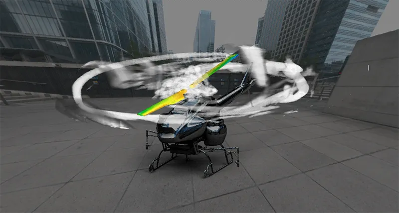
Rotation, pitch, flap and bending happen at once. A deforming mesh tolerates only moderate motion before cell volumes go negative, so blades are meshed overset on a background mesh, as in that paper; the Stuttgart study adds a Cartesian off-body mesh adapted to the vortex structures and a fifth-order scheme. Both run unsteady RANS (Spalart-Allmaras with wall spacing y+ of about 1 in the HART-II study, a k-ω model at Stuttgart), which averages the turbulent fluctuations, so separated flow behind the hub and in deep stall is where we test DES or LES against it. An actuator disk, as in a NASA Ames brownout study, generates no discrete tip vortices: it serves downwash, not blade-vortex questions. We build a mesh and time-step ladder and pick the rung each question needs.
How does CFD/CSD coupling give rotor airloads and trim?
A comprehensive rotor code carries beam-model blade dynamics and trim, but its lifting-line aerodynamics often need tuning. In loose coupling it exchanges with the CFD once per revolution or blade passage: it returns blade motion and trim, the CFD returns airloads. The correction passed back is the CFD airload minus the lifting-line airload of the previous cycle, ΔFi = FCFD,i−1 − FLL,i−1, added to the code's own, Fi = FLL,i + ΔFi, so at convergence it carries the CFD loads.
This is stable and convergent for periodic conditions such as hover and steady flight; a manoeuvre is transient and needs an exchange at every time step. Coupled iterations ran on a medium mesh and the converged blade motion was reused on the finest, since filtering out the interaction changed the final airloads negligibly in a study the paper cites. We script that: a cheap loop, then a fine final run. Agreement was still imperfect: normal force sat offset from the measured mean, tip lead-lag was off by roughly a third of a chord, perhaps from blade stiffness near the root, and trim assumed zero rolling and pitching moments where the test had about 20 N·m. We carry such inputs as ranges.
What causes tail shake, and can CFD predict it?
In fast forward flight the wake of the rotor, hub and airframe strikes the tail boom and excites low-frequency airframe modes. The response is stochastic: the Stuttgart flight-test data show no clear periodicity over 120 s, which rules out a per-revolution exchange. The paper couples a RANS solver at every time step to a modal airframe model (40 modes up to 8/rev, from a Nastran eigenvalue analysis) while the rotor is trimmed periodically with a comprehensive code: about 485 million cells on 24,000 cores.
The low-frequency tail modes fell within the spread of the flight data, but torsion modes came out at slightly lower frequency, one fin sensor's second blade-passing peak was low by an order of magnitude, and damping, taken from shake tests of comparable airframes at 0.02 to 0.08, had to be assumed as 0.04. We treat that as a range.
- Rotor and hub wake. The blades shed tip vortices, and the hub, mast fairing and rotor head shed a turbulent wake of their own. In fast forward flight with low thrust and a slight descent the rotor wake runs low enough to reach the tail, so the hub region has to be in the model, not only the blades.
- Fuselage, engine and skid wakes. Cowling, exhaust, rear fuselage and landing gear add wakes that mix with the rotor wake until the contributions can no longer be separated. The whole aircraft is meshed, and the engine exhaust is a flow condition, not an afterthought.
- Where the wake meets the tail. Unsteady pressure on the tail boom, fin and stabilizer is the forcing. A tail rotor, where fitted, sits in the same region and meets the main rotor tip vortices as well, so its position is part of the question.
- Elastic airframe. The boom bends and twists. The modes that matter are low, of the order of one to two times the rotor frequency, so the structure enters as a modal model from a finite element eigenvalue analysis. Its deflection changes the loads, which is where resonance magnification and aerodynamic damping come from.
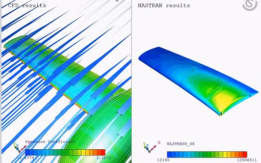
- Exchange at every time step. Surface loads pass from the flow mesh to the matching structural nodes, with a lever arm where a part is missing from the structural model, and modal displacements return to deform the flow mesh. The two discretisations never match node to node, so the link is built by script.
- Response. The response beats and never repeats cleanly, in simulation and in flight-test data alike, so it is compared as spectra over windows of several seconds with no assumed period. The spread between flight-test windows is the yardstick for the comparison.
Few questions need that scale, so we agree with you what each needs: isolated-rotor loose coupling for loads, a whole-aircraft wake over a modal airframe for screening, full time-resolved coupling for the few configurations that decide a design. A tail rotor sits in the same wake and belongs in the study. Load transfer between non-matching meshes is scripted, with a lever arm where the structural model lacks a part, and the airframe model can come from updating as in our ground vibration test article.
What happens on the retreating blade: dynamic stall in rotor CFD
McCroskey's NASA lecture notes give the sequence: stall delayed beyond the static angle, a vortex forming near the leading edge and sweeping back, pitching moment diverging, drag climbing, lift rising until the vortex is well past mid-chord, then dropping. On a model rotor the overshoots excited stall flutter at the blades' torsional frequency, so stall belongs inside the coupled loop. In a loosely coupled study of UH-60A flight data (Potsdam, Yeo and Johnson, 2004, abstract) the dynamic-stall case matched curve shapes but lagged in phase. We validate stall on phase and pitching moment and treat the turbulence and transition model as part of the validation matrix.
Hover and ground effect: what changes in the setup?
Hover sets the power. NASA and Army engineers note that best-case hover predictions have historically been 2 to 5% accurate, that a 2% error in hover power could cost one or two passengers of payload and that 0.5% would be a far better goal (Norman and colleagues, 2023). Figure of merit is FM = (CT/2)1/2 CT/CQ. The Hover Prediction Workshop's open issues include grid independence, temporal accuracy and wake breakdown, so one mesh gives a screening value: we run the ladder and report the uncertainty.
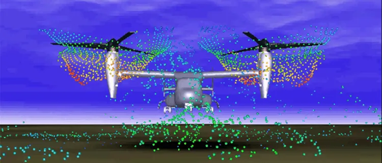
In full-scale tufts on a hovering helicopter, airframe flow grew more unsteady as the rotor neared the ground and ground-plane tufts were extremely unsteady at every height (Wadcock and colleagues, 2008). Brownout-style questions, for helicopters and tiltrotors alike, need the unsteady resolved wake, a statistics window fixed beforehand and a particle model on top.
| Question | Model and coupling | What it reports | Decision it supports |
|---|---|---|---|
| Hover power and wake | Blade-resolved RANS, mesh ladder, trimmed to thrust | Figure of merit, blade loading, wake geometry | Blade planform and twist |
| Forward-flight airloads and vibration | Overset CFD loosely coupled to a rotor code | Section loads by azimuth, blade motion, controls | Blade design before flight test |
| Blade-vortex interaction | Fine mesh along the vortices | Load spikes by azimuth, source data for acoustics | Descent procedure, noise screening |
| Retreating-blade stall | Coupled to elastic torsion | Pitching-moment peaks | Envelope limits, tip and airfoil choice |
| Tail shake | Whole aircraft, tight coupling to a modal airframe | Modal energy, boom spectra | Boom, hub fairing and cowling shape |
| Main and tail rotor interaction | Main-rotor wake reaching the tail rotor | Tail-rotor inflow and loading | Tail-rotor position |
| Ground effect, brownout-style wake | Unsteady wake near the ground, particle model | Outwash and ground-vortex statistics | Landing procedure |
A predicted rotor load is not a clearance
Where does AI help with rotor loads databases, and where does it not?
A loads database spans weight, altitude, speed, thrust, shaft angle and rotor speed. CFD/CSD at every point is out of reach, and the HART II workshop assessment notes that comprehensive codes remain the workhorse where many variations are needed. So we keep them in the loop and put the AI on the correction: a surrogate of the ΔF above over azimuth and radius, trained on designed CFD points. The comprehensive code still solves trim and structure at every query, and a Gaussian-process surrogate returns an uncertainty that shows where the database needs another CFD run.
Blade-vortex peaks and stall onset change sharply with small shifts in wake position or incidence, so held-out CFD points test the surrogate and anything outside its envelope goes to the full chain. It does not extrapolate to a new rotor, and it is not a fatigue or certification statement. See surrogate models for CFD and FEA, AI surrogate models you can sign off and our surrogate modelling and uncertainty quantification pages.
From one rotor study to a rotor-loads workflow you keep
The return comes when your engineers can put the next blade, hub fairing or flight condition through the same chain.
- Physics model. CFD and FEA set up once, as templates: geometry clean-up, mesh, solver settings and post-processing that every later run reuses.
- Validation. Mesh and time-step studies, and comparison with tests or full-scale data, so the model's uncertainty is known before it is trusted.
- Automated runs. Scripted runs over the parameters and operating conditions that matter, on your hardware or in the cloud.
- AI surrogate. A machine-learning model trained on those runs answers in seconds and says how sure it is; low-confidence questions go back to the solver.
- Decision tool. Optimisation, trade-off charts or operating guidance, in a form your engineers and operators use every day.
- Field data. Test, trial and monitoring data flow back to recalibrate the model, so it improves with every project instead of being rebuilt.
- A parametric rotor and airframe model in your solver, with the mesh recipe and the mesh and time-step ladder.
- A coupling script to your rotor code and structural model, with a convergence monitor and the load-transfer map.
- A post-processor for section loads against azimuth, vortex pictures and acceleration spectra.
- A validation record against open data such as HART-II and your tunnel and flight data, tolerances set before the run.
- A surrogate with a stated range and a gate to the full chain.
- Handover and training, so your team runs and extends it. See our training and software development services and the fluid-structure interaction page.
Questions engineers ask about helicopter rotor CFD
What is the difference between loose and tight CFD/CSD coupling?
Can CFD replace wind-tunnel or flight testing of a rotor?
How fine must the mesh be to capture blade-vortex interaction?
Can CFD predict tail shake?
If a blade, hub-fairing or tail-boom change is waiting on a loads or vibration answer, send us the rotor and hub geometry, the flight conditions that matter, the rotor-code deck and structural model you use, and any tunnel, flight-test or loads-survey data. We reply with how we would build the chain, the mesh and time-step ladder, what the validation record should contain and what a surrogate could cover. Start with a conversation, or read the rotor aerodynamics page.