eVTOL rotor noise simulation for the community footprint and the cabin
Many small rotors make a tonal, beating sound that decides vertiport permits and passenger comfort. How unsteady CFD with a Ffowcs Williams-Hawkings analogy, a wind-tunnel validation record and a surrogate with a stated range turn it into a noise budget you can plan with.
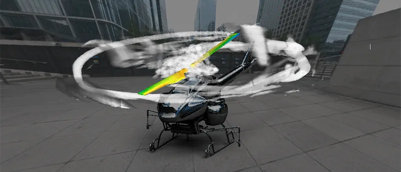
eVTOL noise simulation predicts, rotor by rotor, the tones and broadband sound an aircraft radiates, then carries it to a footprint on the ground and into the cabin. The standard route is unsteady CFD of the rotors feeding a Ffowcs Williams-Hawkings (FW-H) acoustic analogy, checked against wind-tunnel or flight-test microphone data before anyone relies on it.
The noise figure is what the authority and the neighbours read when they decide whether a vertiport gets a permit, how many movements an hour it may handle and at what times of day. It is also what passengers hear. When the first hover test is louder than the target, the remedy is expensive: other blade counts, slower tips, a re-phased control law. How loud is it on the ground, and why does it sound worse than the decibels suggest?
Why is multirotor and tilt-rotor noise hard to predict?
A rotor is a handful of sources that behave differently. Thickness noise comes from the blade displacing air and loading noise from the pressure the blade carries. A steady rotor repeats both every blade passage, so the sound is made of lines at the blade passing frequency fBPF = B·Ω/2π, with B blades at rotation rate Ω, and at its harmonics. Broadband noise comes from turbulence in the boundary layer and wake and from flow leaving the trailing edge; it spreads over many frequencies and does not repeat blade by blade.
A distributed-propulsion aircraft adds interaction sources: a rotor in another's wake sees unsteady inflow, wake over a boom or wing loads the surface, and in transition and descent a blade can pass close to the tip vortex of an earlier one. NASA's quadcopter wind-tunnel tests (Zawodny and Pettingill) found rotor-airframe interaction as high-amplitude harmonics of the blade passing frequency in hover, and rotor wake interaction raising broadband noise in forward flight. NASA's quadrotor noise predictions (Kottapalli and Silva) predicted strong blade-vortex interactions in approach for two of three rotor designs and weak ones for the third. The dominant source changes with the flight condition.
- Tonal noise at the blade passing frequency. Each blade displaces air (thickness noise) and carries a pressure load (loading noise). A steady rotor repeats this every blade passage, so the sound is made of lines at the blade passing frequency, the number of blades times the rotation rate, and at its harmonics.
- Broadband noise. Turbulence in the blade boundary layer and wake, and the flow leaving the trailing edge, make sound spread over a range of frequencies. It does not repeat blade by blade, so it needs a scale-resolving simulation or a separate model.
- Rotor-wake interaction. A rotor in the wake of another, as when a front rotor feeds a rear one in forward flight, sees unsteady inflow. Its blades then load and unload once per wake passage, and that adds tones and broadband sound that the rotor alone would not make.
- Rotor-airframe interaction. Wake washing over a fuselage, wing or boom loads the surface unsteadily, and a blade passing close to a surface sees a changed flow. In NASA wind-tunnel work on a quadcopter, rotor-airframe interaction showed up as strong harmonics of the blade passing frequency.
- Blade-vortex interaction in transition and descent. When a blade passes close to the tip vortex shed by an earlier one, the load changes sharply and the sound is impulsive. It depends on the flight condition, so it has to be checked across transition and approach, not only in hover.
- The listener. What reaches a person is the sum of all these sources, along a direct path and reflected ones, shaped by distance, air absorption, the ground and nearby buildings. Rotors at slightly different speeds make the sum beat, so the level rises and falls.
How is rotor noise predicted with CFD and the FW-H analogy?
CFD cannot carry sound to a listener hundreds of metres away, so the work is split: CFD resolves the flow around the rotors and an acoustic analogy takes it from there. The Ffowcs Williams-Hawkings equation writes the sound as three source terms: a monopole term for the air displaced by the moving surface (thickness), a dipole term for the force on it (loading) and a quadrupole term for the flow volume around it. For a subsonic surface, the solution used for rotor and propeller noise for many years is Farassat's Formulation 1A, derived in Farassat's derivation of Formulation 1A (NASA, 2007). Each observer gets a pressure history.
It works only as far as its inputs. The analogy carries sound; it does not create turbulence. Tones need blade loads at the right phase and enough revolutions to resolve the lines, since frequency resolution is the inverse of the record length. Broadband sound needs scale-resolving turbulence, DES or LES, or a separate model; unsteady RANS gives a good loading history and little broadband sound. Free-space FW-H also knows nothing of reflection from buildings or shielding by the airframe unless they are modelled; NASA's presentation on UAM noise gaps and recommendations (Rizzi and Huff) names scattering and propagation around vehicle components, buildings and vertiports as a gap in the tools, and the need for validation databases to quantify uncertainty.
| Question | Method | Use it when |
|---|---|---|
| What are the tones at the blade passing frequency and harmonics? | Unsteady CFD of the rotors with FW-H, loads resolved in time | Blade count, tip speed or spacing is being chosen |
| How much of it is broadband? | DES or LES with FW-H, or a semi-empirical broadband model | Tones are controlled; the rest is in question |
| What do interactions add? | Multi-rotor and rotor-airframe CFD, in the flight condition that matters | Layout, boom or wing position, or approach is in question |
| How loud is it on the ground, and for how long? | Validated source model propagated along the flight path | Vertiport siting, hours and routes |
| What reaches the cabin? | Airborne and structure-borne paths from rotor and motor forces | Interior noise targets and trim mass |
| Which speeds and phases are quietest? | Validated surrogate, finalists checked in the full model | Speed-schedule design |
Why does eVTOL noise sound worse than its decibel level?
Small rotors turn faster than a helicopter's big one and rarely at exactly the same speed. Two tones close in frequency beat at the difference, so the sound swells and fades, and the higher, more harmonic spectrum adds sharpness and tonality. The evidence is mixed. NASA's HULC psychoacoustic test of UAM vehicles and helicopters found that, at the same A-weighted sound exposure level, UAM vehicles and helicopters produced similar annoyance, and that UAM vehicles were quieter at equal distances. NASA's UAM annoyance model (Boucher et al.) found that a model including loudness, sharpness, fluctuation strength and roughness correlated well with annoyance to a quadrotor, and added a term for tonality. The same NASA presentation notes that current rotorcraft and fixed-wing metrics may not be as useful for UAM noise. Level comes first, but the spectrum and rotor-speed spread are cheap to control early, so we predict them too.
What do EASA and ICAO say about eVTOL noise certification?
ICAO Annex 16 Volume I has no noise standard written for VTOL-capable aircraft, and EASA has so far handled the gap with interim technical specifications. EASA NPA 2025-03 on noise requirements for VTOL-capable aircraft (VCA) proposes a delegated act with noise limits and a standardised method, largely based on Chapters 8 and 13 of Annex 16 Volume I. The proposed metric is EPNL for take-off, overflight and approach, and LAeq for hover. The proposed limits for the three flight procedures are those of Chapter 8 for new helicopters; hover is measured and reported, with no limit. The certified levels are meant as a reference for authorities responsible for land-use planning and operational authorisations. EPNL includes a tone correction to the perceived noise level, so strong tones cost something in the certified number.
Two cautions. The procedures we read are written around measured flight tests; we found no wording that makes a prediction a means of compliance, and the acceptance of any analysis is agreed with the authority. And an NPA is a proposal: its comment period closed on 21 November 2025 and EASA intended to issue an opinion by the fourth quarter of 2026 at the latest, so check where it stands today. Simulation supports test planning, the choice of configurations to fly and the explanation of the result.
A hover match is not a transition match
How do wind-tunnel and flight tests correlate with the prediction?
Test and prediction help each other only if compared the same way: same configuration, microphone positions, rotor speeds and phases. Differences then point somewhere: thrust mismatch to the aerodynamics, a missing harmonic to the mesh or time step, a directivity error to the installation. The facility belongs in the record too, with its background noise, reflections and open-jet shear-layer refraction. Our aeroacoustics and wind tunnel testing work and the aeroacoustics and vibroacoustics practice cover this loop, within the eVTOL, VTOL and UAM hub.
- Templated rotor and vehicle set-up. Geometry, rotor speeds and relative phases, trim and flight condition come from one template, so a run is a change of inputs and every run is set up the same way.
- Unsteady, scale-resolving CFD. The rotors are simulated in time, with DES, LES or unsteady RANS according to what has to be captured. It must resolve the blade loads and the wakes that carry the interaction sources, and the time step and mesh decide which frequencies can be trusted.
- The Ffowcs Williams-Hawkings surface. The acoustic analogy turns the surface pressure on the blades, or the flow on a permeable surface around them, into the pressure signal at each observer. It carries sound from the surface to the observer; it does not make the turbulence that the CFD has to supply.
- The validation gate. Predicted and measured spectra are compared at the same microphone positions: tones at the blade passing frequency and harmonics, broadband level and directivity. A failure sends the work back to the source model and its inputs, and a pass records the range it covers.
- Propagation to an observer grid. The validated source is propagated through the atmosphere to observers on and above the ground. Ground reflection and building shielding need their own treatment; they are not in the source calculation.
- Footprint and metrics. Levels at each ground point are turned into the metric the procedure asks for, such as EPNL or LAeq, and into contours around the vertiport and the flight path.
What reaches the passenger cabin?
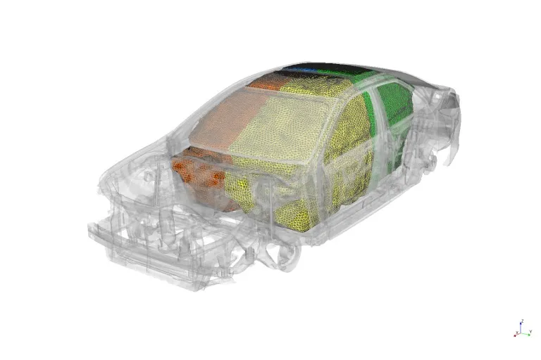
The cabin is a second problem on the same rotors. Pressure pulses at the blade passing frequency and its harmonics load the fuselage skin and reach the interior: the airborne path. Forces from rotors, motors and gearboxes travel through mounts, booms and the frame: the structure-borne path. Both follow rotor speed. The same presentation notes that new tools and methods may be needed for interior noise. Our vibroacoustics performance assessment and NVH analysis of electric motors cover the two paths; panel loading is akin to acoustic-induced vibration.
Where does AI help eVTOL noise work, and where does it not?
- Surrogate noise maps. A surrogate trained on a planned set of CFD-to-FW-H runs predicts directivity or a noise map over rotor speed and phase almost instantly. See surrogate models for CFD and FEA.
- Speed and phase optimisation. A validated surrogate in the loop screens many speed separations and phase offsets for the lowest tonal peaks and beating; the finalists are confirmed in the full model.
- Calibration of source models against test data, returning parameters with their uncertainty.
- An anomaly gate on measured spectra, flagging a tone that does not follow the expected speed-locked pattern before the data is used. See AI surrogate models you can sign off.
Where AI does not help: extrapolating to rotor geometry it has not seen. A surrogate trained on one blade family has learned that family; a new twist, tip shape or blade count is a new problem. Physics supplies the structure, test data supplies the parameters, and the surrogate is delivered with the range it was trained over.
From one noise study to a rotor-noise workflow you keep
The larger return is a workflow your own acoustics team runs, so a new speed schedule, blade count or layout is judged against the same validation record.
- Physics model. CFD and FEA set up once, as templates: geometry clean-up, mesh, solver settings and post-processing that every later run reuses.
- Validation. Mesh and time-step studies, and comparison with tests or full-scale data, so the model's uncertainty is known before it is trusted.
- Automated runs. Scripted runs over the parameters and operating conditions that matter, on your hardware or in the cloud.
- AI surrogate. A machine-learning model trained on those runs answers in seconds and says how sure it is; low-confidence questions go back to the solver.
- Decision tool. Optimisation, trade-off charts or operating guidance, in a form your engineers and operators use every day.
- Field data. Test, trial and monitoring data flow back to recalibrate the model, so it improves with every project instead of being rebuilt.
- A templated rotor and vehicle set-up in your existing CFD solver, with speeds, phases, trim and flight condition as inputs.
- Automated CFD-to-FW-H runs with fixed rules for time step, number of revolutions, surface placement and observers, and the same report every time.
- A validation record against your tunnel or hover-test campaign: microphone positions, tones and bands compared, differences found and the date last checked.
- A surrogate with a stated range for noise maps over speed and phase, with a gate that sends anything outside it back to the full calculation.
- Footprint post-processing into the contours and metrics your noise procedure uses.
- Training and handover, so your engineers can extend the workflow themselves. See our training and software development services.
Questions engineers ask about eVTOL noise
What is the main source of eVTOL noise?
Can CFD predict eVTOL noise?
Does simulation replace the noise certification test?
Why do several small rotors sound different from one big one?
What do you need from us to start?
If an eVTOL noise target is on your desk, send us the rotor layout and the speed schedule, with whatever microphone data you already have from hover or tunnel runs and the procedure the programme must meet. We will reply with how we would build the CFD-to-FW-H chain, which measurements would validate it and what the first calculations would let you decide. Start with a conversation.