Fired heater CFD for burner flames, radiant heat flux and tube-metal temperature
One shield tube runs hot, the burners are due for a swap and hydrogen is on the table, but a zone calculation cannot say where the flame leans. Combustion, radiation and process-side models, each checked, put flame, flux and tube temperature on one chain that feeds FEA for creep.
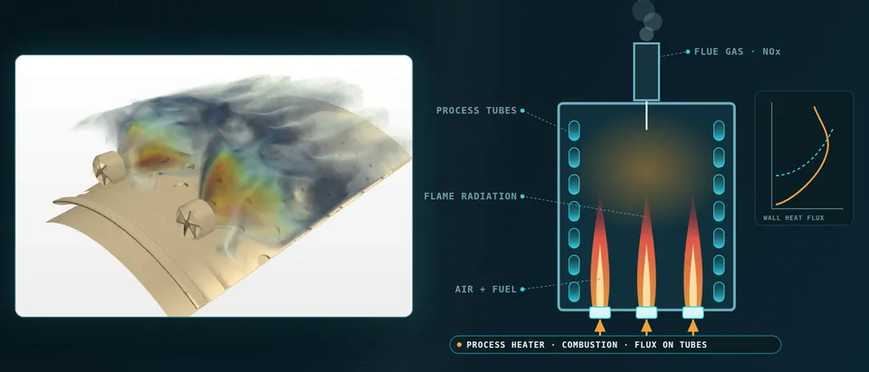
Fired heater CFD predicts how burner flames, flue-gas radiation and recirculation load each process tube, so peak tube-metal temperature, flame impingement and NOx can be compared for a burner swap, a firing-rate increase or a new fuel before the turnaround. It is only as credible as its combustion, radiation and process-side choices, so we build the chain around your existing solver, with a validation record, and pass tube temperatures to FEA for creep.
The infrared survey shows one bright patch on a shield tube, and the run length follows it, not the average. The shutdown window cannot hold both a burner change and a retube, and the heater is asked for more duty, or hydrogen, at the same NOx limit. A zone calculation gets duty and outlet temperature right, as below, but cannot say where a flame leans on a tube.
How does fired heater CFD predict tube-metal temperature?
In a radiant section most heat reaches the tubes as radiation, scaling with σ(Tg4 − Tw4), so a small gas-temperature error becomes a larger flux error. CFD solves the radiative transfer equation, for a grey non-scattering gas (s·∇)I = κ(σT4/π − I), on the real geometry with the computed flame field.
Díaz-Mateus and Castro-Gualdrón (2011), open access, compared RANS CFD with infrared thermography on two refinery heaters. Their tubes are refractory backed, so incident radiation can be several times larger where a tube faces the flame. The zone method with API 530 circumferential factors, which they trace to Hottel curves for only four tube arrangements and none for shield tubes, missed peak skin temperature by a mean of 9% and 10%; CFD stayed within 2%. Both got gas temperature right, because the mean flux heats the feed. The peak sets the metal temperature, and 2% of a kelvin temperature is still 14 to 20 K at 700 to 1,000 K.
- Burner flames. Each burner is a turbulent non-premixed flame whose length and shape follow the mixing of fuel and air. The flame length decides which tubes see it, and its heat release is the source of the whole radiation field, so a wrong flame becomes a wrong flux.
- Gas and flame radiation. Hot CO2, H2O and soot radiate to the tubes and the refractory, which re-radiates. Discrete ordinates with a gas-property model carries this through the real geometry. Emission scales with T4, so temperature errors and turbulent fluctuations are amplified, not averaged away.
- Recirculating flue gas. Cooler gas falls along the walls and is drawn back into the flame roots, diluting them and changing flame length, temperature and NOx. A symmetry plane or a single-burner domain cuts this flow off, so burner-out and uneven-air cases need the full firebox.
- Lean, impingement and interaction. Neighbouring flames entrain from the same space and pull each other over, and a flame that leans lands on a tube and drives a local flux peak. One refinery heater in the open study showed exactly this, a flame deviation with a localised peak that only CFD reproduced.
- Peak flux, not mean flux. A refractory-backed tube takes its flux mostly on the fire-facing side (the crescent), and along the bank the flux has a peak where flame radiation and convection concentrate. A zone model resolves the smooth mean that heats the feed. The peak is what sets metal temperature.
- Process side and fouling. Skin temperature is the flux crossing the wall, the coke or fouling layer and the inside film into the fluid. Those resistances are inputs, not results, so we couple the fire side to your coil or process model and sweep clean and fouled cases.
EDC, flamelet or mixture fraction: which combustion model does the flame need?
A heater flame is turbulent and non-premixed, and mixing mostly sets its shape. Díaz-Mateus and Castro-Gualdrón chose a PDF mixture-fraction model: two transport equations instead of one per species, which matters for a nine-component fuel gas, at the price of equilibrium chemistry, so temperatures and flame patterns are right and intermediates are not, in their words. That suits flame shape and flux, not CO, NOx or a diluted burner.
The eddy dissipation concept (EDC) lets finite-rate kinetics act in fine structures of length fraction ξ* = Cξ(νε/k2)1/4 and residence time τ* = Cτ(ν/ε)1/2; De and Dongre give defaults of 2.1377 and 0.4082. It overshoots where hot flue gas dilutes the flame: for the Delft jet-in-hot-coflow burner they report a peak temperature about 25% above measurement with EDC, about 13% with a multi-environment transported PDF, and a failed scalar field with steady flamelet. Their remedy was a larger chemical time-scale constant. Burners that recirculate flue gas to cut NOx lean toward that regime, so constants belong in validation.
Open benchmarks calibrate judgement. The TNF Workshop archive of the Sandia/TU Darmstadt piloted methane/air flames documents a 7.2 mm nozzle, Reynolds numbers from 13,400 (flame C) to 44,800 (flame F), a pilot near 6% of main-flame power and measured NO. It tests turbulence-chemistry coupling in a free jet; a heater adds confinement, wall-dominated radiation and neighbouring flames, so we verify the set-up on a TNF flame and validate on plant data (see our reacting flows page).
How do you model radiation, soot and the process side of the tube?
Radiation sets the tube flux. The refinery-heater paper and the coke-oven paper below both use discrete ordinates with a weighted-sum-of-grey-gases model; the first found skin temperature sensitive to the angular discretisation and recommends at least 3×3 divisions and pixels. Emission goes as T4, so the mean of T4 is not the fourth power of the mean T, and the TNF radiation page cites a turbulence-radiation study of Sandia flame D. Luminous flames add soot.
The same authors refined the mesh until skin temperatures stopped changing, at 1.8 and 2.5 million cells, held wall y+ between 30 and 300, and judged convergence by one burner's energy imbalance, under 1% of inlet energy after 5,000 to 6,000 iterations.
The tube has a second boundary, the process. Film coefficient, fluid temperature, emissivity (0.94 clean and new, 0.85 fouled and old, in that paper) and above all fouling and coke set the skin temperature, and the authors call fouling resistance purely empirical. They left the hydrocarbon side to a process model; we couple the flux to yours and iterate, so skin temperature is never computed against an assumed film.
How is NOx predicted in a fired heater, and how far can it be trusted?
Thermal NO forms through the Zeldovich reactions, N2 + O ⇌ NO + N and N + O2 ⇌ NO + O, the first with a high activation energy, so NO rises exponentially with the hottest oxygen-rich gas. Prompt NO, from CH radicals in rich zones, depends far less on temperature, and reburn removes NO. NOx is usually post-processed from the flame solution, so the sub-model structure matters.
In a coke-oven heating-flue study, Rossiello and colleagues (2024) obtained 394 mg/Nm3 with reburn and 979 without, against 395 measured: one operating point, with wall heat transfer tuned to a measured brick temperature, so evidence for the model structure, not a prediction band. The TNF radiation page brackets the other effect: an adiabatic calculation is expected to over-predict NO, an optically thin one to under-predict it, a detailed radiation model between. We report NOx as a comparison between burners, fuels or settings on one calibrated model, with the closure spread; the absolute figure belongs to the stack test and the vendor's guarantee.
- Jets and mixing. Fuel and air meet by turbulent mixing, so the dashed mixing layer and the stoichiometric sheet, not kinetics, set where the flame sits and how long it is. Swirl, staging and tile geometry change the mixing, which is why a burner model needs the vendor's near-field data and not a generic flame.
- Recirculated flue gas. Hot product gas is entrained into the jets, diluting the oxygen and lowering the peak temperature, which is how many low-NOx burners work. Dilute, hot-coflow flames are where EDC over-predicts the reaction rate and a single mixture fraction struggles, so the closure is checked here first.
- Hot zone and thermal NO. Where hot gas meets oxygen, the Zeldovich route makes NO, and its rate grows exponentially with temperature (lower right). Radiation lowers that temperature: an adiabatic calculation over-predicts NO, an optically thin one under-predicts it, and a detailed model lies between.
- Fuel-rich side: prompt NO and reburn. In the rich core, hydrocarbon radicals form prompt NO, a route far less dependent on temperature, and they also destroy NO again by reburn. Leave reburn out of the post-processor and the answer can move by a factor of two or more, as in the coke-oven study.
- EDC: a reactor inside every cell. Each cell is split into a fine structure, where finite-rate chemistry acts for a residence time, and surroundings that only mix. Both scales follow from k, epsilon and viscosity through two constants, which is why they are validated and not left at defaults.
- Flamelet: temperature against mixture fraction. A flamelet model stores the flame as a profile of state against mixture fraction, peaking at the stoichiometric value and lowered by strain until it extinguishes. It is cheap and robust for attached flames, but one mixture fraction cannot describe a burner fed by several streams.
What changes when hydrogen enters the fuel gas?
Hydrogen burns faster, over wider flammability limits, and diffuses faster than hydrocarbons, which changes flame length, anchoring and the equal-diffusivity assumption in mixture-fraction models. In a simplified fired-heater burner geometry Weydahl and colleagues (2013) swapped refinery fuel gas for hydrogen at equal power: average wall heat flux was about the same, its distribution changed, and the flame was hotter with comparable NOx; the authors see a significant share of fuel-gas NOx in prompt NO, which hydrogen does not make. The question is where the flux moves.
Which fired heater question needs which model?
| Question | Model | What it reports | Limit to state |
|---|---|---|---|
| Peak tube-metal temperature, run length | Radiant-section RANS, discrete ordinates | Skin temperature around and along tubes | Fouling, coke, emissivity inputs |
| Burner swap, flame impingement | Burner row or firebox, EDC or mixture fraction | Flame envelope, entrainment, lean | Needs vendor near-field data |
| NOx, one burner or fuel against another | Flame solution plus NO post-processing with reburn | Ranking, hot-zone location | Absolute value scatters |
| Hydrogen blend | Same chain, chemistry and diffusion checked | Flux redistribution, flame temperature | Blend limit is the vendor's |
| Firing rate and air ratio over a year | Surrogate on designed CFD runs | Tube temperature, NO maps | Valid inside sampled range |
| Tube creep and thermal stress | CFD temperatures into FEA | Stress, creep damage input | Material data and code route are yours |
How do tube temperatures become creep life?
API Standard 530, seventh edition (April 2015), gives procedures and design criteria for the wall thickness of new heater tubes. Its contents list an equivalent tube metal temperature (5.8), Larson-Miller parameter curves (6.6), an informative annex on maximum radiant-section skin temperature with a figure of the ratio of maximum local to average heat flux (Annex B) and one on allowable skin temperature and remaining life (Annex A). CFD does not replace that route; it can supply the local flux Annex B estimates from a ratio.
We pass the temperature field, around and along each tube, with its uncertainty band, to a thermal-structural model of tubes, supports and bends for thermal stress and creep (see creep and creep-fatigue and our thermomechanical fatigue article). Material data, code route and remaining-life judgement stay with your mechanical-integrity team.
A predicted tube temperature is not a tube-life or emissions guarantee
Where does AI help fired heater design, and where does it not?
- Firing and air maps. A surrogate on designed CFD runs over firing rate, excess air, burner out of service and fuel composition returns tube temperature and NO trends inside its sampled range and gated to the full model outside it.
- Calibration. An inverse fit of emissivity, fouling resistance and the EDC time-scale constant to thermography, thermocouples and stack data returns a range, not a constant.
- The FEA queue. Cases that matter for creep are picked from the map and run in full.
It does not replace the combustion closure, repair a wrong process-side film or extrapolate beyond the sampled burner geometry or hydrogen content. Training data come from designed CFD runs, with physics constraints and a range gate. See surrogate models for CFD and FEA and our surrogate modelling, hybrid physics-AI and uncertainty quantification pages.
From one heater study to a workflow you keep
The return comes when the next burner, fuel or firing case runs through the same chain.
- Physics model. CFD and FEA set up once, as templates: geometry clean-up, mesh, solver settings and post-processing that every later run reuses.
- Validation. Mesh and time-step studies, and comparison with tests or full-scale data, so the model's uncertainty is known before it is trusted.
- Automated runs. Scripted runs over the parameters and operating conditions that matter, on your hardware or in the cloud.
- AI surrogate. A machine-learning model trained on those runs answers in seconds and says how sure it is; low-confidence questions go back to the solver.
- Decision tool. Optimisation, trade-off charts or operating guidance, in a form your engineers and operators use every day.
- Field data. Test, trial and monitoring data flow back to recalibrate the model, so it improves with every project instead of being rebuilt.
- A parametric heater model in your existing solver, with one template recording combustion, radiation, mesh and convergence choices.
- A burner data library of vendor near-field data, flame-shape checks and fuel compositions.
- A verification case: a TNF flame re-run after every model or solver change.
- A process-side coupling script with clean and fouled cases.
- A NOx post-processor with a reburn switch and recorded spread.
- A validation record against your thermography, skin thermocouples, outlet temperatures and stack O2 and NOx, tolerances set before the run.
- A surrogate with a stated range and a gate to the full model.
- Handover and training; see our training and software development services.
Questions engineers ask about fired heater CFD
Is CFD more accurate than API 530 for tube skin temperature?
EDC or flamelet for a fired heater?
Can CFD predict NOx for a permit?
Can I model one burner and use symmetry?
If a burner change, a firing-rate increase or a hydrogen blend waits on a tube-temperature answer, send us the heater arrangement, burner datasheets with fuel compositions and firing cases, your thermography, thermocouple and stack data, and the coil data. We reply with the model chain we would set up, the validation we would run first and what a surrogate could cover. Start with a conversation, or read our reactor design and combustion and heat transfer equipment pages.