Plasma etching simulation from reactor flux to trench profile for ICP and CCP tools
The recipe clears the trench at the wafer centre and leans at the edge, and chamber B no longer matches A. Reactor plasma models, sheath energy and angle distributions and feature-scale profiles show which flux, charge or reaction is responsible.
Plasma etching simulation predicts what an ICP or CCP tool delivers to the wafer, ion and radical fluxes and the ion energy and angle at every radius, and what the feature does with them: taper, bowing, notching, charging. We build it as a repeatable chain around your existing solver, with a validation record and a surrogate of stated range, so more of a recipe or chamber-matching question is answered before wafers are committed.
The recipe clears the trench at the wafer centre. At the edge the sidewall leans, and since the last wet clean chamber B no longer matches chamber A. Kanarik and colleagues (Nature, 2023) put one experiment above a thousand dollars, counting wafer, tool time and microscopy, and note that engineers typically test about a hundred of the potentially many trillions of combinations of pressure, powers, gas flows and wafer temperature. Release, qualification and transfer dates wait on that handful.
What does plasma etching simulation have to predict?
Two models and one hand-over. The reactor model delivers reactive fluxes to the wafer with their energy and angular distributions; the feature model takes them in and moves the surface, as Krüger and colleagues (2024) describe it. The scales do not share a clock: at 13.56 MHz the RF period is about 74 ns, the gas stays in the chamber far longer, and a process runs for seconds to minutes. Each scale gets its own model; the hand-over table is a versioned, tested interface.
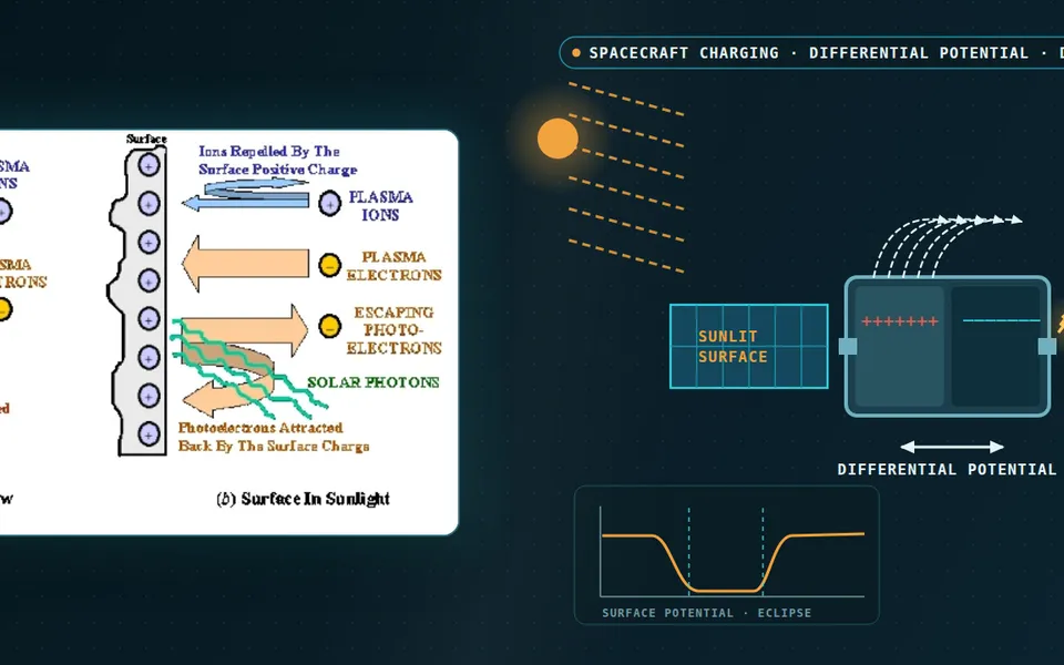
- Source power makes the plasma. The coil drives an alternating current whose magnetic field induces the circulating electric field drawn as dashed loops. The plasma absorbs it within a skin layer near the dielectric wall, and at low pressure the electron heating is non-local. The generator reading is not the power the plasma absorbs, because matching and coil losses sit between them, so absorbed power is a quantity we calibrate.
- Gas, dissociation and pumping set the radicals. Feed gas is dissociated into radicals that diffuse and ride the flow, the travelling dots, over the wafer and out to the pump. The wafer and the walls consume them, so their radial profile depends on flow, pressure and on wall material and conditioning. Electronegative gases add negative ions that reshape the plasma profile.
- The sheath turns plasma into an ion beam. Ions enter the sheath at the Bohm speed and cross it under the sheath voltage. The space-charge-limited current follows the Child-Langmuir law, so a denser plasma gives a thinner sheath at the same voltage. The sheath edge follows the surface, and ions fall along the local field.
- Bias power sets the ion energy. The bias generator drives the chuck, and the voltage that develops across the sheath, not the source power, sets the energy ions carry to the wafer. Source and bias are nearly independent knobs, not fully independent, and the sheath model has to use the real waveform, not a sine.
- Energy and angle, not one number. Whether ions follow the instantaneous sheath voltage depends on their transit time, τ, against the RF period, T. For τ below T the energy distribution is double-peaked, the solid curve; for τ above T it is one narrow peak, the dashed curve. Collisions in the sheath lower energies and widen the angles, so the lobe alternates between narrow and broad. Both distributions are the feature model's input.
- Uniformity is a reactor result. Fluxes and ion angles change from centre to edge, and a different recipe changes the shape of the profile, recipe A against recipe B. Where the surface steps up to the focus ring the sheath edge bends and ions arrive tilted, the amber arrows, so a feature at the edge leans. The flux map and the distributions at each radius are what we hand to the feature model.
How do reactor models get ion flux and uniformity right?
Power first: a frequency-domain electromagnetic solve gives the coil's induced field, with the plasma as a complex conductivity. Low-pressure heating is non-local, which a local conductivity misses, and the generator reading is not the absorbed power, so we calibrate that. Heavy-particle fluid equations are sound where collisions dominate, but the electron energy distribution is not Maxwellian, so a kinetic electron module or Boltzmann solver supplies rate coefficients. Krüger and colleagues couple such modules by time slicing.
A global model, volume-averaged particle and power balance, screens chemistries in seconds but has no radial profile. Particle-in-cell with Monte Carlo collisions needs no Maxwellian assumption, at a cost that keeps it to the sheath or a small reactor. Turner and colleagues ran four capacitive-discharge cases in helium, simple geometry and chemistry, through five independently developed PIC codes and found them statistically indistinguishable within defined bounds. We run any code we build or wrap on such cases first.
The sheath makes the distribution. Ions enter at the Bohm speed, (kTe/M)1/2, and the space-charge-limited current across a planar collisionless sheath, J = (4/9)ε0(2e/M)1/2V3/2/s2, ties its thickness s to voltage and density. Whether ions follow the RF voltage is a race between transit time τ and RF period T: for τ < T the energy distribution is double-peaked, for τ > T narrow. At the wafer edge, where the surface steps to the focus ring, the sheath bends and ions arrive tilted.
Why do trenches taper, bow and notch?
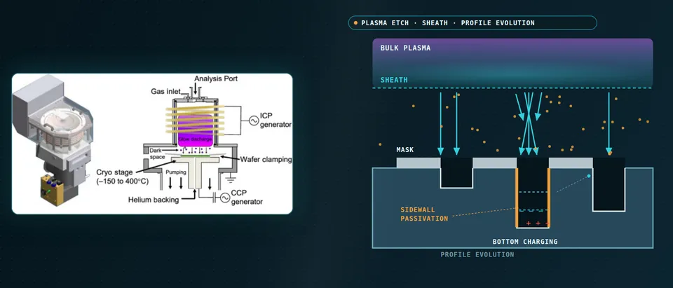
In the feature the roles reverse. Neutrals travel straight between wall collisions at etch pressures, so flux to the floor and etch rate fall with depth: aspect-ratio-dependent etching. Ions are directional, not perfectly: energy above a threshold removes material, angular spread puts some on the wall. Passivation protects the wall; too much necks the mask opening, then clogs it. Krüger and colleagues note that 3D-memory features now approach an aspect ratio of 100.
Charging closes the loop. Electrons arrive isotropically and stop at the top of an insulating mask; ions arrive directionally and reach the floor. The mask charges negative, the floor positive, until the field deflects ions into the lower wall: notching at the foot, bowing and twisting higher up. Charge depends on profile and profile on charge, so they are solved together.
Krüger and colleagues list level-set, voxel Monte Carlo and molecular-dynamics feature models, the last limited in feature size and by potentials for complex chemistries. Kanarik and colleagues run a level-set model on a 25 nm grid for a virtual hole etch: ±2 nm variability on a typical run, under ten minutes per case on 16 cores. Resolution is a budget decision we set against your tolerance.
- Ions arrive with the reactor's energy and angle. The ion energy and angle distribution from the reactor model is the input. Ions above a threshold energy remove material and drive the surface chemistry, and the angular spread decides how many strike a sidewall instead of the floor.
- Neutral flux starves with depth. Neutrals arrive from all directions and, at etch pressures, travel straight between wall collisions. The flux to the floor falls as the trench deepens, the fading shade and the dots that bounce down the walls, and the etch rate falls with it: aspect-ratio-dependent etching. The curve shows the trend only.
- Electrons charge the mask, ions the floor. Electrons arrive isotropically and stop at the top of the mask, which charges negative. Ions arrive directionally and reach the floor, which charges positive over an insulating stop layer, until the field starts to bend the ions.
- Deflected ions bow and notch. Ions bent by the field strike the lower sidewall, the amber paths, and remove extra material: a notch at the foot of the wall and bowing higher up. The profile alternates with and without it. Charge depends on the profile and the profile on the charge, so they are solved together.
- Passivation protects, then necks. A deposited film coats the sidewall and protects it from lateral etching. The same deposition on the mask corner narrows the opening, called necking, and in the worst case closes it, called clogging, which stops the etch.
- Reaction set: ranges, not points. Each surface reaction has a probability, a yield that depends on ion energy and angle, and a threshold energy. Many are poorly known, so we carry them as ranges, the bands, sample them, the travelling dots, and fit the sensitive ones to SEM cross-sections at more than one condition, the fixed dots.
How do you couple reactor and feature models without paying for both every time?
One-way coupling answers most questions: the reactor runs to quasi-steady state, fluxes and distributions by wafer radius go to the feature model as a table. Two-way coupling is needed only where the wafer changes the plasma, as a large etched area consumes radicals. Walls are the other open boundary: radical recombination depends on liner material and history, so wall coefficients are ranges. When chamber B drifts from A, measured hardware differences enter as parameters and name which one moves which flux.
Which etch question needs which model?
| Question | Model | Reports | Limit to state |
|---|---|---|---|
| Is flux uniform across the wafer? | Axisymmetric reactor model, EM solve, kinetic electrons | Flux and angle maps by radius | Chemistry, wall coefficients, absorbed power |
| What energy and angle do ions carry? | Sheath model with the real RF waveform: PIC-MCC | Distributions per radius | Collisions, waveform |
| Will this trench taper, bow or notch? | Feature model with charging | Profile against time | Coefficients calibrated on SEM data |
| Does rate fall with aspect ratio? | Feature-scale neutral transport | Rate against depth | Sticking and re-emission data |
| Why does chamber B not match A? | Parametric reactor model, measured hardware | Flux change per hardware change | Needs chamber data |
| Sweeps over power, pressure, flow | Surrogate on designed runs | Rate, uniformity, width maps | Sampled range only; gate to full model |
How reliable are gas-surface reaction sets, and what do you do about it?
Turner (2016) studied a helium–oxygen chemistry of almost four hundred reactions, not an etch chemistry, and found that only about fifty rate constants materially affect the results and as few as ten cause most of the uncertainty. Earlier work he reports found predictive uncertainty of a factor of ten or more in some cases. The lesson: screen for the few coefficients that matter before spending wafers.
Krüger and colleagues calibrated a feature mechanism with poorly known reaction probabilities against one SEM image of a silicon dioxide etch in a C4F6/Ar/O2 capacitive discharge, matching the feature to within 1% on their geometric metrics. Outside the training conditions it reproduced the onset of clogging as gas ratio and low-frequency power changed, and etch-rate trends less well. They treated the reactor fluxes as true and left the sensitivity to them open, so reactor errors can hide in the coefficients, and they warn of overfitting on small data. We calibrate only sensitive coefficients, within physical bounds, at several conditions, hold one back and report ranges, as in our chemical reactor CFD article.
A calibrated profile is not a qualified process
Where does AI help plasma etch design, and where does it not?
- Surrogates over power, pressure and flow. Trained on designed reactor and feature runs, they return flux maps, etch rate and width inside a stated range, with a gate to the full model. Xiao and colleagues, reviewed by Trieschmann, Vialetto and Gergs, used recurrent-network surrogates of a fluid plus kinetic Monte Carlo etch model for predictive control of etch depth and bottom roughness.
- Recipe search. Kanarik and colleagues compared engineers with Bayesian optimisation on a virtual hole etch: algorithms alone beat the expert on cost in fewer than 5% of trajectories, an expert-first, algorithm-last strategy halved the cost to target, and for retuning such as chamber matching the authors expect the algorithm to take over sooner. The engineer's constraints go first, a calibrated physics model behind.
- Uniformity under uncertainty. Jung and colleagues fit a heteroscedastic Gaussian process to etched depth at nine wafer locations, separating variability across the wafer from process uncertainty in pressure, gas flow and RF power.
- Discrepancy learning. The review notes that systematic gaps between process and model can be learned from data; we fit that gap as a bounded correction, never a replacement for the physics.
It does not repair a wrong reaction set or carry a surrogate beyond its range. Pamarty and colleagues predicted etch-rate maps of a capacitive RIE tool from sensor data on 17 training wafers; test recipes outside and at the edge of the training range had far worse error than the one inside. Ours state the range and send cases outside it to the full model. See our surrogate modelling, hybrid physics-AI and uncertainty quantification pages and our articles on surrogate models and validating them.
From one etch study to a workflow your team keeps
The return comes when your engineers run the next recipe or chamber through the same chain.
- Physics model. CFD and FEA set up once, as templates: geometry clean-up, mesh, solver settings and post-processing that every later run reuses.
- Validation. Mesh and time-step studies, and comparison with tests or full-scale data, so the model's uncertainty is known before it is trusted.
- Automated runs. Scripted runs over the parameters and operating conditions that matter, on your hardware or in the cloud.
- AI surrogate. A machine-learning model trained on those runs answers in seconds and says how sure it is; low-confidence questions go back to the solver.
- Decision tool. Optimisation, trade-off charts or operating guidance, in a form your engineers and operators use every day.
- Field data. Test, trial and monitoring data flow back to recalibrate the model, so it improves with every project instead of being rebuilt.
- A parametric reactor model in your existing solver: coil or electrode, gas injection, pumping, liners and power as parameters, one template recording solver, chemistry and mesh choices.
- A hand-over contract: fluxes and distributions by wafer radius in a versioned, tested file.
- A feature template and reaction library, each coefficient with source, range and sensitivity rank.
- A validation record against SEM cross-sections, etch-rate maps and the probe or emission data you hold, tolerances set before the run.
- A scripted chamber-difference study of two tools.
- A surrogate with a stated range and a gate to the full model.
- Handover and training, so your team runs and extends it: our training and software development services.
How credible is a plasma etch simulation result?
Verification is convergence: mesh and time step in the reactor model, particle count and noise in Monte Carlo and PIC, grid and noise band in the feature model. Validation uses data you hold or can generate: SEM cross-sections at several conditions, etch-rate maps, probe or emission data, one condition kept back. Uncertainty is sampled: sensitive reaction and wall coefficients, absorbed power, the numerical band. The answer is a range with ranked contributors.
Questions engineers ask about plasma etching simulation
Can plasma etching simulation predict a new recipe's profile?
Fluid or PIC for an ICP etch reactor?
What is aspect-ratio-dependent etching?
How does reactor simulation help chamber matching?
Does simulation replace wafer lots or qualification?
If a recipe release, a tool transfer or a chamber-matching problem is waiting on this, send us the film stack and mask layout, the gas chemistry and process window, a chamber drawing, and the SEM cross-sections and uniformity maps you hold. We reply with the model chain we would set up, the validation we would run and what a surrogate could cover. Start with a conversation, or see our plasma etching simulation page.