Gear whine simulation, from transmission error to radiated and cabin noise
Gear whine starts as a tiny transmission error at the mesh and ends as noise at the casing and in the cabin. A checked chain from tooth contact through flexible shafts and housing finds the tone before micro-geometry and tooling are frozen.
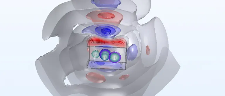
Gear whine simulation predicts the tone a gear pair makes by computing its transmission error under load, carrying the resulting mesh force through shafts, bearings and a flexible housing, and ending in radiated or cabin noise. We build that chain around your existing multibody and finite element solvers, so tooth micro-geometry, bearing stiffness and housing ribs are settled before gears are ground and a casting tool is cut.
The first prototype gearbox passes its durability cycle and fails on the NVH rig: a clean tone that rises with speed, loud at part load, quieter at full load, and louder in some build units than in others. The micro-geometry is on the grinding drawing and the housing tool is ordered. An electric drive has no combustion noise to mask a mesh tone. The review asks which stage makes it, whether teeth, shafts or housing are to blame, and what removes it at every torque the vehicle uses.
What is gear whine, and why is it hard to predict?
Gear whine is the tone at the tooth-mesh frequency, fm = z n / 60 for z teeth on a shaft turning at n rev/min, and at its multiples. Its source is transmission error. Zakrajsek, Oswald, Townsend and Coy at NASA Lewis (NASA TM-102435, 1990) define it as the deviation of the output gear's angular position from the ideal, caused by manufacturing errors and elastic deflection of the teeth. Real teeth bend under load, and mesh stiffness changes as load passes between one and two tooth pairs.
Along the line of action the pair acts as one oscillator: me x″ + c x′ + k(t) [x − e(t)] = F. Here x is the relative displacement of the teeth, e(t) the unloaded error, me = I1I2 / (I1rb22 + I2rb12) the effective mass from the gear inertias and base radii, and F the mean tooth load. Both k(t) and e(t) repeat once per mesh, so the force reaching the shafts has lines at fm, 2fm, 3fm, with sidebands at shaft orders from eccentricity and pitch error.
Two things make it hard. The best micro-geometry depends on torque: the NASA Lewis studies of gear noise and vibration found parabolic tip relief less sensitive than linear relief to changes in load, in the amount of relief and in its length, so relief tuned at one torque can leave a tone at another. And the contact depends on misalignment under load, which neither the gear model nor the housing model holds alone.
- Tooth contact and line of action. The tooth force acts along the line of action, tangent to both base circles. Torque sets its mean; what shakes the shafts is its fluctuation once per tooth mesh.
- Mesh stiffness cycle. The stiffness of the teeth in contact changes as the load passes between one and two tooth pairs and as the contact moves along the flank. A spur gear steps; a helical gear, whose teeth enter contact gradually, varies less. A stiffness that repeats once per mesh is a source in itself.
- Transmission error. The deviation of the driven gear from the position perfect, rigid teeth would give, measured along the line of action. Loaded, it holds tooth deflection and manufacturing error; tip relief and crowning are chosen to flatten it, and the best choice depends on torque.
- Mesh harmonics. A periodic error gives lines at the tooth-mesh frequency, the tooth count times the shaft speed, and at its multiples. On a run-up they are straight order lines, as in a Campbell diagram.
- Sidebands. Eccentricity, runout and pitch error modulate the mesh, putting sidebands at shaft orders either side of each harmonic. Tones that no tooth count explains can come from the machine that cut the gear, not from the design.
- Backlash and rattle. The clearance between flanks. When torque fluctuation exceeds the torque a lightly loaded pair carries, the teeth separate and strike the other flank: broadband clatter, an impact problem rather than a harmonic one.
How is gear whine usually found, and where does that break?
The usual route splits the problem in three. A gear specialist tunes micro-geometry in a contact program at the design torque, on rigid supports. A driveline team runs a rigid multibody model for torsional dynamics. The NVH team tests the first prototype and answers with ribs, mass or mount changes. Each hand-off drops something.
Misalignment costs most. The Lewis group reports that spur gears are very sensitive to it: contact shifts towards the tooth edge and transmission error rises, and crowning the pinion reduces the sensitivity. In a real gearbox it comes from shaft bending and housing deformation under torque, so a gear model on rigid supports tunes the crowning for a misalignment the gearbox does not have. The split also hides a harmonic that meets a housing mode on one stretch of the speed range, and the unit-to-unit scatter from tolerances. The cost arrives late: a regrind, ribs added to a casting tool, a rejected end-of-line batch.
How do you simulate gear whine from the mesh to the cabin?
We build the chain in four stages, with a check on every hand-off. Hambric and colleagues, in a NASA report on a rotorcraft transmission noise path (NASA/CR-2010-216812), describe the same structure: housing and shaft modes from finite element models are reduced by component mode synthesis so bearing impedances can be changed quickly; dynamic loads representing the gear transmission error drive the assembled model at the meshing teeth; and a boundary element model turns housing vibration into radiated sound. They compared the result with mesh tones measured on a test gearbox.
- Loaded tooth contact. A contact analysis gives static transmission error and mesh stiffness for each roll angle over a grid of torques, with micro-geometry and misalignment as parameters. Check: contact pattern and error against a roll test or an independent solver.
- Flexible multibody model. Shafts are beams, bearings are stiffness and damping matrices, and the housing is a Craig-Bampton flexible body, u = Ψ ub + Φ q: static constraint modes Ψ at the bearing seats and mounts, fixed-interface normal modes Φ. In Simpack, MSC Adams or your existing solver the gear pair takes k(t) and e(t) from stage 1 and runs up through the speed range. Check: housing modes and mobilities against a modal test of the real casting.
- Radiation. Housing surface velocity drives a boundary element or finite element acoustic model. The Hambric report cites work confirming that boundary element models compute gearbox radiated sound accurately when the surface vibration is known. Check: sound intensity or microphone data around the casting.
- Mounts and cabin. The forces also leave through the mounts and subframe into the body, a structure-borne path separate from the air-borne one, which our powertrain NVH work follows to the occupant. Check: transfer function across the mount and an interior order cut.
Then the loop closes. Bearing-seat displacements from stage 2 go back to stage 1, one iteration at each torque point, so load, misalignment and contact pattern stay consistent. The Hambric report also shows why each harmonic is run separately: on their test gearbox, measurement and model agreed that journal bearings lowered the second mesh harmonic and gave no clear benefit at the fundamental.
- Mesh force. The tooth force pushes pinion and wheel apart along the line of action. Its time history comes from the contact model: stiffness and transmission error for each roll angle, at the torque being run.
- Shafts and bearings. Shafts bend and bearings carry the force into the casing. Bearing stiffness and damping, often nonlinear with preload and clearance, are the coupling between mesh and housing, and they change the tones differently at different harmonics.
- Flexible housing. The casing is reduced with the Craig-Bampton method: static constraint modes at the interface nodes, here the bearing seats and mounts, plus fixed-interface normal modes. A few modal coordinates then carry its dynamics inside the multibody model.
- Radiated sound. Surface velocity of the housing drives an acoustic model, boundary element or finite element, that gives the sound the casing radiates. Panels and ribs that move together radiate most.
- Mounts and cabin. Vibration also leaves through the mounts into the subframe and body: a structure-borne path, separate from the air-borne one, and either can set the level at the occupant.
- Loop back to the mesh. Shaft bending and housing deformation change the misalignment of the teeth, so the contact pattern and the transmission error depend on them. The deflections must return to the contact model, at each torque, not only the forces go out.
What about gear rattle and clatter?
Rattle is the opposite of whine: a lightly loaded problem. When torque fluctuation from the engine or motor exceeds the mean torque the pair carries, the teeth leave contact, cross the backlash and strike the other flank. The NASA report on the non-linear dynamics of geared systems (Singh, Houser and Kahraman, NASA CR-4338, 1990) models a spur pair with backlash and periodically time-varying mesh stiffness, and defines mathematical conditions for tooth separation and back collision.
The response is impact-driven, not harmonic, so it needs a time-domain multibody model with a contact law for the flanks, the drag torque of idle gears and the real torque source. In an electric drive that source includes motor torque ripple, which our electric motor NVH article follows from slot and pole numbers; here it is an input to the gear train.
| Symptom | Likely source | First model to run |
|---|---|---|
| Tone at a fixed multiple of speed, loud at one torque only | Micro-geometry tuned for another load | Loaded transmission error over a torque grid |
| Tone that peaks in one speed band | Mesh harmonic meeting a shaft, housing or mount mode | Order map: harmonics against assembled modes |
| Sidebands around the mesh tone | Eccentricity, runout or pitch error | Tolerance study on the contact and flexible model |
| Tone at an order no tooth count explains | The machine that cut or ground the gear | End-of-line spectra against the expected orders |
| Clatter at light load that fades with torque | Backlash and torque fluctuation | Time-domain model with flank contact and drag torque |
| Cabin loud, housing quiet | Structure-borne path through the mounts | Mount transfer and body vibroacoustics |
| Whine differs between build units | Tolerance scatter on lead, profile and preload | Surrogate of the harmonics with sampled tolerances |
Do not tune micro-geometry on a rigid housing at one torque
Where does AI help gear whine simulation, and where does it not?
- A surrogate of mesh stiffness and transmission error harmonics over micro-geometry, torque and misalignment, trained on a planned set of contact analyses, so a micro-geometry search becomes affordable. See surrogate models for CFD and FEA.
- A surrogate of the housing transfer, from mesh force per order to surface velocity or radiated power, over rib layout and wall thickness.
- Tolerance scatter: grinding and assembly deviations sampled through the surrogate give the spread of tone level between units, which sets tolerances and the end-of-line limit.
- Calibration of bearing stiffness, damping and mount rates from run-up and modal data, a Bayesian fit returning parameters with their uncertainty. See AI surrogate models you can sign off.
Where it does not help: impact physics. Rattle in an irregular regime, or edge contact under misalignment, lies outside what a surrogate trained on smooth cases has seen. The surrogate has a stated range, and a request outside it goes back to the solver. A tone no tooth count explains is a question for the machine that cut the gear: an anomaly gate on end-of-line spectra finds it.
From one whine investigation to a driveline NVH capability you keep
The return comes when your own team runs the chain for the next ratio, housing or e-axle.
- Physics model. CFD and FEA set up once, as templates: geometry clean-up, mesh, solver settings and post-processing that every later run reuses.
- Validation. Mesh and time-step studies, and comparison with tests or full-scale data, so the model's uncertainty is known before it is trusted.
- Automated runs. Scripted runs over the parameters and operating conditions that matter, on your hardware or in the cloud.
- AI surrogate. A machine-learning model trained on those runs answers in seconds and says how sure it is; low-confidence questions go back to the solver.
- Decision tool. Optimisation, trade-off charts or operating guidance, in a form your engineers and operators use every day.
- Field data. Test, trial and monitoring data flow back to recalibrate the model, so it improves with every project instead of being rebuilt.
- A parameterised gear-to-housing chain in your existing solvers, with micro-geometry, bearings and rib layout as parameters and the hand-off checks scripted.
- Automated order maps over torque and speed: mesh harmonics against the modes of shafts, housing and mounts for every design change, with crossings ranked.
- A correlation record: roll-test, modal and run-up data per gearbox variant, and the bearing and mount properties fitted from them.
- A surrogate with a stated range over micro-geometry, torque and tolerances, with a gate that returns out-of-range requests to the full model.
- Handover and training, so your engineers extend it themselves. See our training and software development services.
Questions engineers ask about gear whine
What causes gear whine?
What is transmission error, and how is it found?
Why does whine change with torque?
Can simulation predict gear whine before a prototype exists?
What do you need from us to start?
If a gearbox or e-axle is on your desk, send us the gear data and micro-geometry, the shaft and bearing layout, the housing model, the torque and speed duty, and the order cut that worries you. We will reply with how we would build the chain, which hand-off we would check first, which measurement would calibrate it and what the first order map would let you decide. Start with a conversation, or read about our multibody dynamics and NVH work and the multibody dynamics section.