Electric motor NVH in eVTOL aircraft, from stator force order to cabin whine
The whine and vibration of a propulsion motor are set by magnetic force orders meeting structural modes. How a checked chain from electromagnetic force to airframe and cabin finds them before the motor design and mounts are frozen.
Electric motor NVH in an eVTOL is the tonal whine and the vibration produced when the magnetic force on the stator, set by the slot and pole combination and the inverter current, excites structural modes of the motor, its mounts and the airframe. We predict it with a checked chain from electromagnetic force to structure to cabin, so tones can be moved before design and mounting are frozen.
The discovery is usually late. A bench run or first hover test shows a pure tone that follows speed, or a buzz felt through the seat, and the winding, brackets and cabin treatment are already fixed. The remedies cost what an aircraft can least afford: mass for damping, a re-wound or re-skewed stator, a carrier frequency that moves heat into the inverter, or a restricted speed range. The review questions are plain. Which tones will occupants hear, at which speeds, and is the cause in the motor, the mount or the airframe?
Why is electric motor NVH harder in an eVTOL than in a car?
Three things change. First, there is usually no gearbox: a propeller or fan on the motor shaft means the motor runs at propeller speed, which in many designs is the control variable for thrust. A direct-drive motor therefore sweeps across a wide speed range in normal flight, and every force order crosses every structural mode inside that range. Second, the motor is built for power per kilogram, so its stator, housing and brackets are thin and light, and thin structures have dense modes in the audible range. Third, there are several lift and thrust units. EASA's means of compliance (MOC-4 SC-VTOL) notes that variable-speed units can produce a greater range of harmonic frequencies with different phases between units, and asks that their effect be investigated.
Cluts et al. (NASA Glenn, 2021) report, in a paper on surface vibration and electric motor noise for UAM and UAS, that outrunner motors of the kind used on urban air mobility vehicles may contribute to cabin noise. They measured rotor vibration on two small-scale motors, and their finite element predictions of rotor resonance roughly matched, with discrepancies left to study. The chain works, and it needs test data to be trusted.
Where does electromagnetic whine come from?
The air gap carries a flux density with normal and tangential components Bn and Bt. The Maxwell stress on the stator surface is σ = (Bn2 − Bt2)/(2μ0) normal to the surface and BnBt/μ0 along it. The normal part is the radial force that deforms the stator. Because it depends on the square of the field, a field that varies as cos(pθ − ωt), with p pole pairs, gives a force that varies as cos(2pθ − 2ωt): a pattern of spatial order 2p, equal to the number of poles, at twice the electrical frequency. That order is high, and a stiff stator barely responds.
The trouble comes from the other products. Slotting, winding and current harmonics and eccentricity combine with the main field and give force components of low spatial order. For the main interaction, the lowest non-zero spatial order is commonly the greatest common divisor of the slot number Q and the pole number 2p; a 12-slot, 10-pole machine gives order 2, the oval deformation of the stator that is easiest to excite. The same numbers set the cogging torque, with a number of periods per revolution equal to their least common multiple. Fractional-slot concentrated windings favour torque density and are a usual source of low-order forces, so the slot and pole choice is an NVH decision as much as a torque one. Skew and winding choices change their amplitudes.
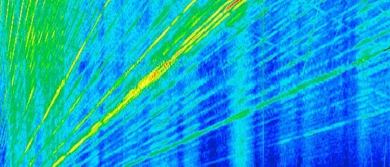
- Force orders. Each electromagnetic force component has a frequency that is a fixed multiple of the rotation speed, so on a run-up it is a straight line through the origin. Which orders carry energy follows from the slot and pole numbers, the winding and the current waveform.
- Stator and housing mode. A structural mode has a nearly fixed frequency, a horizontal line. The relevant one is the mode of the stator core, windings and housing as assembled, not of the bare core, and its shape has a spatial order.
- Resonance crossing. Where a force-order line meets a mode line inside the speed range that is flown, the response is amplified. It matters only if the spatial shape of the force also matches the shape of the mode, and it is removed by moving the mode, the order or the speed range.
- Mount and panel mode. A lower mode of the mounting, bracket or airframe panel. It decides how much vibration leaves the motor as a structure-borne path into the cabin, whatever the motor radiates itself.
- Operating band. With a direct-drive propeller and thrust set by speed, the motor sweeps through a wide speed range in normal flight, so the orders cross every mode that lies inside it. The band is the part of the plot that is actually flown.
- PWM carrier family. In a fixed-carrier drive, switching harmonics sit near multiples of the carrier frequency, which does not follow the motor speed, with sidebands spaced by multiples of the fundamental. They are the high, steady part of the whine.
What happens when a force order meets a structural mode?
A force of spatial order r and frequency f excites a mode of the same shape r near f. Both conditions must hold: a crossing with the wrong shape is harmless, and one with the right shape is amplified inversely with the damping, which is low in a motor. We read the crossings from an order map, then move the mode by stiffness or mass, move the order by skew or winding, or move the speed range, if the flight envelope allows it.
Two points decide whether the map can be trusted. The modes that matter are those of the assembled stator, windings, housing and mount, and they depend on joint stiffness that a drawing does not contain. And damping is measured: Cluts, Henderson and Busch (NASA Glenn, 2025) state, in their semi-empirical model of motor surface vibration, that accurate prediction depends on good damping values, and they measured it for 1 to 5 kW class motors.
What do PWM switching and torque ripple add?
An inverter does not deliver a sine wave: its switching ripple adds force components near multiples of the carrier frequency, with sidebands spaced by multiples of the fundamental. In a fixed-carrier drive these tones do not follow motor speed, and sound like a steady high-pitched whine under the speed-dependent ones. Carrier frequency and modulation are chosen for losses and heat, as our power electronics thermal design article describes, and the same choices move the noise. Torque ripple, from cogging and current harmonics, acts through the shaft and the mount reaction, so the model carries torque as well as radial force.
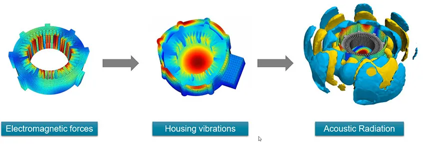
How should an electric motor NVH simulation chain be built and checked?
Each hand-off gets its own check before the next stage is trusted. We start with the electromagnetic model, transient or harmonic, driven by the real current waveform with its switching ripple, and extract the force on the teeth per spatial and time order, with the torque. The first check is that the force integrates to the torque the model gives by another route. The force is mapped onto the structural mesh, and the second check is that the mapped force still adds up to what was exported. The structural model, with housing, mount stiffness and damping, gives the modes and forced response, and the third check is that its modes agree with a modal test of the assembled motor. The last step carries the vibration into airframe and cabin, as in our vibroacoustics performance assessment work, and compares it with a run-up measured with order tracking.
- Current and switching. The phase current carries the fundamental and the switching ripple of the inverter. Both set the magnetic field, so the current waveform is an input to the noise model, not a detail of the drive.
- Force on the teeth. The Maxwell stress on the stator tooth surfaces gives a radial force pattern around the air gap. Its spatial order follows from the slot and pole combination, its frequency from the current and the rotor position.
- Mapping to the structure. The force is exported per order and mapped onto the structural mesh. The check is that the mapped force still adds up to the force and torque the electromagnetic model computed.
- Stator, housing and mounts. The structural model carries the stator and housing modes as assembled, with the mount stiffness and damping. A force order that meets a mode of the same spatial shape is amplified.
- Airframe and cabin. Vibration enters the airframe through the mounts and radiates from panels into the cabin, while the motor also radiates directly. A vibroacoustic model carries both paths to a point at the occupant.
- Test correlation. A run-up test with order tracking, and a modal test of the assembled motor and mount, are compared with each stage. They calibrate damping and mount stiffness and show which stage is wrong when the cabin does not agree.
See our NVH analysis for eVTOL and electro-motors, electric motor NVH and electrical motor design pages, and the eVTOL, VTOL and UAM section.
| Symptom | Likely source | First model to run |
|---|---|---|
| Tone that follows motor speed at a fixed multiple | Force order meeting a stator or mount mode | Order map: harmonic force against assembled modes |
| Tone at a steady frequency whatever the speed | Inverter switching harmonics and sidebands | Electromagnetic model with the real switching waveform |
| Tone that peaks only in a narrow speed band | Resonance crossing | Modal and forced response of the assembled stator and mount |
| Tone that changes with torque, not only speed | Load-dependent harmonics and saturation | Electromagnetic model at several load points |
| Buzz in the seat or the propeller shaft | Torque ripple and cogging | Torque model and mount reaction path |
| Loud panel, quiet motor | Structure-borne path through the mounts | Mount transfer and airframe vibroacoustics |
Do not read resonance from the modes of the bare stator
What does the regulator ask for, and what can simulation support?
The EASA Special Condition VTOL (SC-VTOL-02, Issue 2, 10 June 2024) requires in VTOL.2160 that each part of the aircraft be free from excessive vibration throughout the limit flight envelope, and in VTOL.2400(c)(4) that the lift and thrust installation account for vibration and fatigue. The Fourth Publication of Means of Compliance with the Special Condition VTOL (MOC-4 SC-VTOL, Issue 2, 11 July 2025) says that VTOL.2160 is a flight requirement that includes the effect on crew and occupants, and describes determining the natural frequencies of the structure or installation by instrumented ground vibration testing and comparing them with the relevant sources of vibration, with further substantiation such as instrumented flight test if they fall within the source range.
Analysis does not replace that demonstration. It supports it: it tells the test team which speeds and structures to instrument, which crossings to expect and whether a design change has moved them, and it makes the ground vibration test more informative. Whether any analysis is accepted as a means of compliance is agreed with the authority for your programme.
Where does AI help electric motor NVH, and where does it not?
- A surrogate of the force-order amplitudes and the modal response over slot, skew, magnet and current parameters, trained on a planned set of electromagnetic and structural runs, so a design sweep becomes affordable. See surrogate models for CFD and FEA.
- Calibration of mount stiffness and damping from modal and run-up data, an inverse problem whose Bayesian fit returns the parameters with their uncertainty, which then carries into the cabin prediction.
- Multi-objective optimisation of slot, pole and skew choices with a validated surrogate in the loop, trading torque, losses, mass and tones, with finalists confirmed in the full chain.
- An anomaly gate on run-up spectra that compares each new motor with the order map, so a tone that should not be there is caught on the test stand. See AI surrogate models you can sign off.
Where it does not help: replacing the coupling between a force order and a mode. That physics has a sharp condition, spatial shape and frequency together, and a model trained on one family of motors will not know the mode of an unseen bracket. The surrogate carries a stated range, and requests outside it go back to the solver.
From one noise investigation to a motor NVH capability you keep
The return comes when your own team runs the chain for the next winding or bracket, with every answer checked the same way.
- Physics model. CFD and FEA set up once, as templates: geometry clean-up, mesh, solver settings and post-processing that every later run reuses.
- Validation. Mesh and time-step studies, and comparison with tests or full-scale data, so the model's uncertainty is known before it is trusted.
- Automated runs. Scripted runs over the parameters and operating conditions that matter, on your hardware or in the cloud.
- AI surrogate. A machine-learning model trained on those runs answers in seconds and says how sure it is; low-confidence questions go back to the solver.
- Decision tool. Optimisation, trade-off charts or operating guidance, in a form your engineers and operators use every day.
- Field data. Test, trial and monitoring data flow back to recalibrate the model, so it improves with every project instead of being rebuilt.
- A parameterised motor model chain in your existing solvers: slot, pole, winding, skew and current as parameters, exporting force per order to a structural template, with the hand-off checks scripted.
- Automated order maps: for every design change, the force orders against the modes of the assembled stator, housing and mount over the flown speed range, with crossings ranked.
- A correlation record: run-up and modal test data for each motor variant, and the damping and mount stiffness fitted from them.
- A surrogate with a stated range for force-order amplitudes and modal response over geometry and current parameters, with a gate that returns out-of-range requests to the full model.
- Handover and training, so your engineers extend it themselves. See our training and software development services.
Questions engineers ask about electric motor NVH
What causes the whine of an electric motor?
How are radial force harmonics and stator modes linked?
Can simulation predict motor whine before a prototype exists?
How do PWM settings change motor noise?
What do you need from us to start?
If a propulsion motor is on your desk, send us the slot and pole numbers, winding and skew, inverter carrier and speed range, the mount concept, and a run-up spectrogram or modal test if you have one. We will reply with how we would build the chain, which hand-offs we would check first, which measurements would calibrate it and what the first order map would let you decide. Start with a conversation.