Hot stamping simulation of martensite, cycle time and tool cooling before try-out
A press-hardened part gets its strength from cooling in the die, not from the coil. How a coupled thermo-mechanical-metallurgical model, a measured heat transfer coefficient and a conjugate tool-cooling study turn that into strength, cycle time and tool cost you can plan.
Hot stamping simulation predicts, in one coupled model, how an austenitised boron steel blank cools through transfer, forming and the closed-die quench, how much of it becomes martensite and where, and how long the press must hold. We use it to set tool cooling and cycle time and to give the crash team a believable strength map before the tool is cut.
A press-hardened pillar or rail is bought for its strength, and that strength is not in the coil. It is made in the die, by cooling. When try-out shows a soft corner, a hold time that holds the line below its parts-per-hour target, or a part that will not sit in the gauge, the remedy is in tool steel: channels re-drilled, an insert replaced, a launch date moved. The design-review questions are plain. Will it reach full hardness everywhere? How fast can we run it? Will the cooling channels we drew do their job?
Why is hot stamping simulation harder than cold forming simulation?
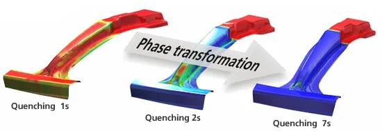
Three problems are solved in the same elements at the same time. Thermal: the thin blank loses heat to air during transfer and to the tool once the die closes, ρcp∂T/∂t = ∇·(k∇T) + ΣLi∂fi/∂t, where the last term is the latent heat of the transformations, and heat crosses the interface as q″ = h(Tblank − Ttool). Mechanical: flow stress depends on temperature, strain rate and strain, and the blank is formed while it cools. Metallurgical: the phases that form decide hardness, and they also add strain and heat. Total strain carries thermal and transformation strain and transformation-induced plasticity on top of the elastic and plastic parts, so the cooling path sets distortion as well as strength.
The model has to follow the whole sequence: furnace austenitisation, transfer, forming, quench under closing force, hold and removal. Karbasian and Tekkaya (2010), A review on hot stamping, Journal of Materials Processing Technology 210 reviews the process, and Merklein et al. (2016), Hot stamping of boron steel sheets with tailored properties: a review, Journal of Materials Processing Technology 228 reviews how tailored properties are produced.
How is the martensite fraction predicted in hot stamping?
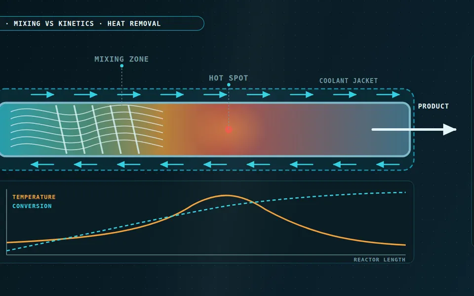
Whether a point ends up hard depends on whether its own cooling path misses the nose of the diffusional curve on the continuous-cooling transformation (CCT) diagram.
- Austenitised blank and transfer. The blank leaves the furnace fully austenitic and cools slowly in air on its way to the press. The longer the transfer, the lower the temperature at which the die closes and the closer the starting point sits to the nose.
- The nose of the diffusional curve. Ferrite, pearlite and bainite form by diffusion, so they need time. The curve bounds where they can start, and its nose is the shortest time at which they can. It moves with chemistry, austenite grain size and any strain held in the austenite.
- Fast path: contact in the die. Pressed hard against a cold tool, the blank cools steeply, passes to the left of the nose and reaches the martensite start temperature with austenite intact. Below it, martensite forms by shear, following the Koistinen-Marburger relation.
- Slow path: gap or poor contact. Where the blank springs off the tool, meets a wide clearance or sits on scale, the interface coefficient falls, the path bends into the curve and soft diffusional products form. The part is soft exactly where the contact was worst.
- Tailored path: a heated tool segment. A tool section held warm, or without cooling, slows the quench on purpose. The path enters the lower flank of the curve and holds at a bainite temperature, giving a softer, more ductile zone in a chosen place.
- Ms line: latent heat and strain. Below the martensite start temperature the austenite shears and expands, releasing latent heat and adding a transformation strain that, with transformation-induced plasticity, is what distorts the part and warms it locally.
There is no single critical cooling rate to take from a handbook. It depends on chemistry, austenite grain size and austenitising practice, and strain held in the austenite can shift the diffusional transformations, so forming and quench cannot be treated as separate steps. A calibrated model carries the CCT behaviour of your coil instead. Ferrite, pearlite and bainite form by diffusion, with Avrami-type kinetics, f = 1 − exp(−k·tn), where k and n depend on temperature; the additivity rule advances them along a changing temperature by summing the fraction of the incubation time used up until it reaches one. Martensite is displacive: it depends on undercooling, not time, and follows fm = fγ·{1 − exp[−α(Ms − T)]}, the relation of Koistinen and Marburger (1959) in Acta Metallurgica 7, with fγ the austenite left at Ms. Hardness is commonly taken as a rule of mixtures over the phase fractions, calibrated against hardness traverses or tensile tests on a formed part.
Why does the heat transfer coefficient decide the result?
Every prediction above inherits the interface. The coefficient h rises with contact pressure and falls with any gap; it changes with coating or oxide scale and with the surface temperature of the tool. And the blank does not sit flat on the tool everywhere: side walls, radii and thin sections see lower pressure and more clearance. A constant h gives a smooth, optimistic answer, and the slow region is rarely where you expect it. The remedy is to measure it. Instrumented-tool trials, with thermocouples in tool and blank, give h as a function of pressure by inverse analysis, and the model is then checked on a different part or condition than the one it was calibrated on.
| Question | Model | Use it when |
|---|---|---|
| Is the blank too cold when the die closes? | Thermal model of transfer, with emissivity and oxide | Transfer time or furnace-to-press layout is in question |
| Does every region reach full martensite? | Coupled forming and quench, calibrated kinetics, h(p, gap) | Part strength or soft spots are the worry |
| Where do channels go, and how long is the hold? | Conjugate tool and coolant model over several cycles | Tool design, cycle time and tool cost |
| Where will it warp, and why does it not fit the gauge? | Thermo-mechanical model with transformation strains, through to room temperature | Fit, joining and assembly tolerances |
| Where should a soft zone sit? | Tailored tool segments with temperature or hold as parameters | The crash design asks for a ductile region |
| How will the formed part behave in a crash? | Hardness map passed to the crash mesh | Release of the crash model for sign-off |
How do tool cooling channels set hot stamping cycle time?
After forming, the cycle is mostly waiting. The press holds until the slowest region of the part has cooled through its transformation and is stiff enough to leave the die, and transfer, closing and opening add the rest. Shortening the hold is therefore a tool-cooling problem, and tool cooling is conjugate heat transfer: conduction in the tool steel, convection in the channel, coupled through the interface. Distance from channel to surface and spacing between channels set how evenly the surface cools. Flow rate sets the coolant-side film coefficient, but once that film is not the bottleneck, more flow buys pumping power and little else; the conductivity of the tool steel and the interface decide the rest. Coolant also warms along a series circuit, and the tool itself heats over repeated strokes, so the study must run several cycles. It is the same physics as in our heat exchanger article, applied to a die.
- The hot blank. An austenitic blank is formed and then held under pressure in the closed die. Everything after closing is heat extraction: the blank has to drop through the transformation range fast enough, everywhere, before the die can open.
- The contact interface. Two rough surfaces touch at a few points, so heat flows mainly through the contacts. The coefficient h rises with contact pressure and falls with any gap, and a coating or oxide layer adds resistance. It is the least certain input in the whole model.
- Cooling channels. Distance from channel to working surface and spacing between channels set how evenly and how fast the tool surface cools: closer channels extract faster but print stripes of temperature into the surface and take away tool material.
- Heat path through the tool steel. Heat crosses the interface, conducts through the tool steel and is picked up by the coolant. The tool steel conductivity and the path length are as important as the coolant flow rate.
- Tailored zone. Heater cartridges and an insulating slit replace channels in one section, so the blank there cools slowly, transforms to softer phases, and the part gets a ductile zone by design.
- Coolant circuit. Coolant warms along its length, so a long series of channels cools the last channel less than the first. The tool and the coolant are one conjugate heat transfer problem, and the cycle time follows from it.
Do not tune channels on a uniform heat transfer coefficient
Soft zones, coatings and distortion: what else must the model get right?
- Tailored properties. A heated or uncooled tool segment, or a slower local quench, gives a softer zone on purpose. The model must place the transition between hard and soft where the crash design wants it, and keep it there as the tool warms.
- Coating and oxidation. A coated blank and a bare blank differ in emissivity during transfer and in interface resistance during the quench, so each needs its own card. Scale adds a resistive layer at the interface.
- Distortion. Thermal gradients and the expansion at Ms leave residual stress and shape error in the part. Our sheet metal forming and stress-relief and heat-treatment work cover the same chain for springback and residual stress, and the metal forming simulation section places this process among the others.
How does the strength map reach the crash model?
The output the crash team needs is not a colour plot but a property map on their mesh. We map hardness or phase fraction onto the crash model and convert it to yield and tensile strength with a correlation measured on your coil. Rate dependence and failure still need their own tests, as described in our crash simulation credibility checklist, and soft-zone transitions are the places to check first.
Where does AI help hot stamping simulation, and where does it not?
- Calibration. Fitting h(p, gap) and the kinetics parameters to instrumented-tool and dilatometry data is an inverse problem. Bayesian calibration returns the parameters with their uncertainty, which then carries through to the prediction. See hybrid physics-AI modelling.
- A surrogate of the martensite and hardness map against transfer time, austenitising, hold time, tool temperature and interface scale, trained on a planned set of coupled runs. See surrogate models for CFD and FEA.
- Channel-layout optimisation with a validated surrogate in the loop, so hundreds of layouts are screened and the finalists are confirmed in the full model.
- An anomaly gate that compares line data, such as die temperature, hold time and coolant outlet temperature, with the prediction, and flags a drifting tool before parts go soft. See AI surrogate models you can sign off.
Where AI does not help: replacing the transformation physics when the data covers one steel and one tool. A surrogate cannot invent the CCT diagram of a coil it has not seen, and it extrapolates badly to a new coating or a new tool. Physics supplies the structure, data supplies the parameters, and the surrogate is stated with the range it was trained on.
From one hot stamped part to a press-hardening capability you keep
One part studied once answers one question. The larger return comes when the set-up becomes a workflow your own team runs, so the next part, coil or tool revision costs days of calculation, not weeks of try-out, and every answer is checked the same way.
- Physics model. CFD and FEA set up once, as templates: geometry clean-up, mesh, solver settings and post-processing that every later run reuses.
- Validation. Mesh and time-step studies, and comparison with tests or full-scale data, so the model's uncertainty is known before it is trusted.
- Automated runs. Scripted runs over the parameters and operating conditions that matter, on your hardware or in the cloud.
- AI surrogate. A machine-learning model trained on those runs answers in seconds and says how sure it is; low-confidence questions go back to the solver.
- Decision tool. Optimisation, trade-off charts or operating guidance, in a form your engineers and operators use every day.
- Field data. Test, trial and monitoring data flow back to recalibrate the model, so it improves with every project instead of being rebuilt.
- A validated material and transformation card library. Flow stress, CCT-based kinetics, latent heat and transformation strains for each coil and coating you run, with the dilatometry or trial data behind them and the date they were last checked.
- A templated coupled model for transfer, forming and quench in your forming solver, with the interface coefficient as a function of pressure and gap, so a new part is set up from the template rather than from scratch.
- Automated cooling-channel studies over distance, spacing, flow and tool temperature, run over several press cycles, reporting hold time and the worst-cooled region.
- A surrogate with a stated range for the martensite and hardness map against cycle parameters, with a solver gate that sends out-of-range requests back to the full model.
- A hand-over to the crash team: the hardness map mapped onto the crash mesh with your property correlation, scripted and versioned.
- Training and handover, so your engineers can extend the workflow themselves. See our training and software development services.
Questions engineers ask about hot stamping simulation
What is hot stamping, or press hardening?
Can simulation predict hardness and martensite fraction?
How do you shorten hot stamping cycle time?
Why is the heat transfer coefficient so uncertain?
What do you need from us to start?
Our sheet metal forming work, the metal forming simulation section and the wider thermal analysis practice cover this ground. If a press-hardened part is on your desk, send us one part number, its coil data and the tool cooling layout, together with the hardness traverse or cycle log from your last trial. We will reply with how we would build the model, which measurements would calibrate it and what the first results would let you decide. Start with a conversation.