Robot dynamics simulation for payload, cycle time and tool vibration
A robot that meets its payload rating can still miss its cycle time, because the tool keeps ringing after every stop. How a checked multibody and finite element model finds torque limits, joint flexibility and settling time before the cell is built.
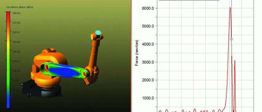
Robot dynamics simulation predicts, before commissioning, how a robot moves with its real payload: the torque each axis needs, how much the joints and links flex, and how long the tool centre point rings after a stop. We build it as a checked multibody and finite element model, so cycle time, payload and actuator choices rest on the dynamics and not on the datasheet.
The cell passed on paper. The payload rating covers the new gripper, and the offline program fits the takt time. On the floor the tool keeps moving after every stop, and the camera, dispense head or weld waits for it to settle. The usual repair is to slow the program, which costs throughput on every part for the life of the line. What will this robot really do, and what has to change: payload, speed, reducer, trajectory or controller setting?
Why does a robot that meets its payload rating still miss its cycle time?
A payload rating says what the robot may carry. Cycle time depends on how fast it may carry it and how soon the tool is still. For a rigid arm with joint angles q the equation is M(q)q̇̇ + C(q,q̇)q̇ + g(q) = τ − τf. Payload mass, centre of gravity and tool inertia enter the inertia matrix M and the gravity term g, so they set the torque at every acceleration. The wrist axes feel an offset gripper first.
That equation has no compliance, and it cannot explain a tool that rings. Between each motor and its link sits a reducer with finite torsional stiffness. In the simplest flexible-joint model the motor angle θ and the link angle q are tied by a spring: Jθ̈ + k(θ − q) = τ, and M(q)q̈ + C(q,q̇)q̇ + g(q) = k(θ − q), with J the motor inertia seen at the link side. For one joint the resonance falls at ω = √(k(1/J + 1/M)), where M is the link inertia. M changes with pose and payload, so the resonance moves when the arm stretches or the gripper changes, and a model checked at one pose says little about the next. W. J. Book, “Controlled motion in an elastic world” (NASA NTRS, 1992) presents the flexibility of drives and structures as the obstacle in high-performance motion systems, particularly manipulator arms.
- Motor side. The motor and the input of the reducer carry the rotor inertia and receive the torque the servo drive commands. The servo loop sees the motor angle, not where the tool is.
- Joint stiffness and damping. The reducer, bearings and housing act as a torsional spring and damper between motor and link. The link can lag the motor and oscillate against it, so the tool does not stop when the motor does.
- Link side and its load. The inertia the joint drives depends on the pose, because reach changes, and on the payload. The resonance of the pair moves with both, so a measurement at one pose does not describe the next.
- Flexible links. The arm segments bend and twist under acceleration. Their modes come from a finite element model, reduced to a few shapes the multibody solver can carry through the whole motion.
- Payload and tool. Mass, centre of gravity and inertia of the gripper, process head and part enter the equations at the flange. The dashed outline is where a perfectly rigid tool would be; the real one swings about it.
- Tool-centre-point ringing. After a stop the tool centre point oscillates and the oscillation decays with the damping. The process may start only once it stays inside its tolerance band, so this trace sets part of the cycle time.
What belongs in a robot dynamics simulation model?
Everything that changes the answer to your decision:
- Payload: mass, centre of gravity and the inertia tensor of tool and part.
- Joints: motor and reducer inertia, torsional stiffness and damping, and friction that depends on speed and temperature.
- Links: bending and twisting modes of each arm segment, from a finite element model reduced to a few shapes. See our robots dynamics and performance assessment page.
- Drive and controller: servo loop, current limits, trajectory generator and filters. Where controller code can be co-simulated through the Functional Mock-up Interface (FMI) standard, we use it; where the firmware is closed, we fit its measured response.
- Process loads: gun reaction, contact force or a payload that changes mid-move.
We build around the tools you already run: Simpack or MSC Adams for the motion, Ansys or Abaqus for the link models. The multibody dynamics hub shows how they are coupled.
How is tool-centre-point vibration judged?
By the quantities your acceptance test already uses. The scope of ISO 9283, Manipulating industrial robots: performance criteria and related test methods (1998 edition, scope clause) lists the characteristics it specifies and tests: pose accuracy and repeatability, position stabilization time, position overshoot, path accuracy, path velocity characteristics, minimum posing time, static compliance and weaving deviations. It does not say which to choose for a given robot, and it requires the same test loads, velocities, paths and cycles when robots are compared. The model should therefore report settling time and overshoot for a stated payload, speed and path, so prediction and floor measurement answer the same question.
Where does the usual approach to robot cycle time break?
- Datasheet scaling. An offline simulator moves a kinematic robot at a percentage of rated speed, with no joint compliance, true payload inertia or thermal limit.
- Tuning on the floor. Acceleration is reduced until the ringing stops. That works for one robot and one tool, lives in the programmer's head, and starts again with the next gripper.
- One checked point. A model matched to one pose and payload is trusted at all of them, while the resonance moves with both.
- A study nobody can rerun. The model stays with the specialist who built it.
The cost arrives after the robot size is chosen, the layout frozen and the takt time promised. The options left are a slower line, a larger robot or a redesign.
How do you check the model before trusting a cycle time?
Verification comes first. With the joint stiffness made very large the model must return the rigid-body result, and a free swing must conserve energy apart from the damping put in. Validation then needs three measurements: motor current logs for a known move and payload, which test inertia, gravity and friction; a tool accelerometer record of stops at several poses, which tests resonance and damping; and the same moves with a second payload. A Bayesian fit of stiffness, damping and friction to those records returns them with their uncertainty.
Stiffness varies with pose, payload, temperature and wear, so the predicted settling time is a band, and the decision uses its upper end. See how we validate AI and surrogate models for the same discipline applied to surrogates.
- Commanded velocity. The planner accelerates, cruises and decelerates within the limits it is given. Shorter moves spend most of their time accelerating and braking, where the torque is highest.
- Motor torque. Torque is inertia times acceleration plus gravity and friction. A heavier or more offset payload raises the acceleration and braking plateaus (dashed), and the wrist axes feel the tool inertia first.
- Torque limits. The drive has a peak torque, and the motor has a continuous rating set by heating, judged on the root mean square of the torque over the cycle. A move must fit both, and the dashed lines stand for them.
- Ringing after the stop. Joint and link compliance keep the tool moving after the motors have stopped. The oscillation decays with the damping, at a frequency set by stiffness and load inertia.
- Tolerance band and process start. A weld, a dispense, a camera shot or a placement needs the tool inside a tolerance. The process starts where the envelope of the ringing enters the band and stays there.
- Shorter cycle. A command shaped to the measured resonance, or a retimed acceleration, reduces the ringing, so the process starts earlier without raising the torque peaks. The model checks that before it reaches the robot.
Can one model give cycle time, energy and actuator size?
Yes, because they are one torque history read three ways. Its peak meets the drive and reducer limits. Its root mean square, τrms = √((1/T)∫τ2dt), is compared with the continuous rating of the motor, since heating follows current squared. Torque times speed gives mechanical power and the energy per cycle. A sweep of payload and timing shows which axis and move set the limit. The drive's own heating is treated in our power electronics article. The same run gives the loads in the arm, which feed fatigue assessment of links, reducers and brackets under durability and fatigue life, so a faster program does not quietly shorten the life of the arm.
| Decision | Model that answers it | Trust it when |
|---|---|---|
| Does the new gripper keep the cycle time? | Rigid-body dynamics with payload mass, centre of gravity and inertia, plus torque limits | Motor torque for a logged move matches the model |
| Why does the tool ring and wait after a stop? | Flexible-joint multibody model with tool-centre-point output | Resonance and damping match accelerometer records at several poses |
| Which robot size or reducer is enough? | Torque history of the cycle: peak and RMS against the ratings | Friction and inertia are fitted to current logs, with ranges |
| Can the path stay accurate at higher speed? | Flexible joints and links with the servo loop | Path and overshoot match a test run to the same conditions as ISO 9283 |
| Which payloads and programs can the cell accept? | Surrogate of cycle and settling time over the payload range | The request is inside the stated range, otherwise it goes to the full model |
| Will the arm last at the new speed? | Flexible links reduced from finite element models, with joint and tool loads out | Link modes match a hammer or shaker test |
Do not quote a cycle time from the rigid-body model
Where does AI help robot dynamics simulation, and where does it not?
- A surrogate of cycle and settling time over payload mass, centre-of-gravity offset, tool inertia, acceleration limits and pose region, trained on planned runs of the validated model, so a program or payload sweep is quick. See surrogate models for CFD and FEA and our reduced-order modelling page.
- Calibration of stiffness, damping and friction from current logs and tool accelerometer records, returning each with its uncertainty.
- Optimisation of acceleration profiles and move timing under a settling constraint and the torque limits, with finalists confirmed in the full model.
- A digital twin that runs the model against controller logs and flags drift in friction or stiffness, an early sign of reducer wear. See digital twins and predictive maintenance.
Command shaping is where the model pays back directly. D. P. Magee, “Dynamic control modification techniques in teleoperation of a flexible manipulator” (NASA NTRS, 1991) presents an input-shaping method to remove end-point vibration from a flexible manipulator while keeping its motion useful. A shaping filter is only as good as the resonance it is given, which is why the pose-dependent resonance has to be right.
Where AI does not help: finding a resonance it has never seen. A surrogate trained on one tool family knows nothing about the flexible bracket of a new gripper, so it carries a stated range and sends requests outside it back to the solver.
From one cell study to a robot dynamics capability you keep
The return comes when your own engineers check the next gripper, payload or program in an afternoon, with every answer carrying the same checks.
- Physics model. CFD and FEA set up once, as templates: geometry clean-up, mesh, solver settings and post-processing that every later run reuses.
- Validation. Mesh and time-step studies, and comparison with tests or full-scale data, so the model's uncertainty is known before it is trusted.
- Automated runs. Scripted runs over the parameters and operating conditions that matter, on your hardware or in the cloud.
- AI surrogate. A machine-learning model trained on those runs answers in seconds and says how sure it is; low-confidence questions go back to the solver.
- Decision tool. Optimisation, trade-off charts or operating guidance, in a form your engineers and operators use every day.
- Field data. Test, trial and monitoring data flow back to recalibrate the model, so it improves with every project instead of being rebuilt.
- A parameterised robot-cell model in your existing solver: payload mass, centre of gravity and inertia, tool, joint stiffness and the move list as inputs, with torque and tool-centre-point outputs scripted.
- A validation record per robot type: current logs and tool accelerometer records for stops at several poses and payloads, and the stiffness, damping and friction fitted from them, with their ranges.
- Automated sweeps over payload, tool and program that report the cycle-time band, peak and RMS torque margin and settling time, and rank the moves that limit the cell.
- A surrogate with a stated range for cycle and settling time over payload and timing parameters, with a gate that returns out-of-range requests to the full model.
- Log readers and handover: scripts that turn controller exports into the validation record, and training so your team extends the model itself. See our training and software development services.
Questions engineers ask about robot dynamics simulation
What is robot dynamics simulation?
How does payload change robot cycle time?
Why does a robot tool vibrate after it stops, and can simulation reduce it?
How much of the cycle is settling time?
What do you need from us to start?
If a robot cell is on your desk, send us the robot type, the tool and payload data, a representative program, the tolerance at which your process may start, your cycle target, and any current log or accelerometer record of a stop. We will reply with how we would build the model, the three measurements that would validate it, where it would sit in your program release, and what the first run would let you decide. Start with a conversation.