Vehicle dynamics simulation that turns ride and handling into virtual road loads
A full-vehicle multibody model with checked tyres, roads and flexible chassis parts gives ride, handling and the component loads that durability needs, before the first prototype reaches the proving ground.

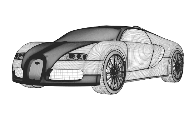
Vehicle dynamics simulation is a multibody model of the whole vehicle, with suspension, steering, driveline, tyres and the flexible parts of the chassis, driven over a road or through a manoeuvre to predict ride, handling and the force in every component. Built and checked properly, it gives you virtual road loads for durability and seat vibration before a prototype has driven a metre, so decisions that are expensive to reverse are taken on evidence.
The usual sequence is familiar. Hardpoints and bush rates freeze with the body structure. The first prototype goes to the proving ground with wheel force transducers, and the loads that come back drive the subframe and bracket fatigue calculations. Then a cracked mount or a shake at the steering wheel appears when the only remedies are a heavier part, a retuned damper or another test campaign, and a new battery mass or tyre supplier restarts the campaign. The review questions are plain. How many prototypes and track days do we need? Can we release the subframe tooling? Why does it shake on this road and not on that one?
What does a vehicle dynamics simulation model contain?
The vehicle is a set of rigid and flexible bodies joined by kinematic joints and force elements: links, bushings, springs, dampers, bump stops, anti-roll bars, steering, driveline and powertrain mounts, with the tyres as the only contact with the ground. The equations are the multibody form M(q)q″ + ΦqTλ = Q with the constraints Φ(q,t) = 0, integrated in time while a driver or manoeuvre controller closes the loop (primes are time derivatives). ISO 8855 provides the common vocabulary for this field, from axis systems to suspension and steering geometry, so that a term such as toe change under load means the same to analyst and test engineer.
The smallest useful model shows why ride is a compromise. A quarter car has a sprung mass ms on a spring ks and a damper c above an unsprung mass mu carried by the tyre stiffness kt:
ms zs″ + c(zs′ − zu′) + ks(zs − zu) = 0, and mu zu″ − c(zs′ − zu′) − ks(zs − zu) + kt(zu − zr) = 0,
where zr is the road height. It has two modes, body bounce at low frequency and wheel hop much higher, and damping that tames one changes the other. The full vehicle adds pitch, roll, steering, driveline and mount modes. The same quarter-car idea sits inside standard road roughness indices.
- Road input. The vertical profile under the wheel drives the model. It is measured on your routes or proving ground, or generated to match the statistics of a road class, and checked against the measurement before any load is trusted.
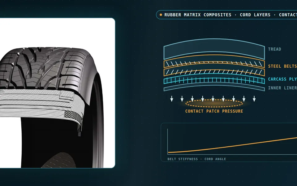
- Tyre and contact patch. The tyre is the only link between road and vehicle. A slip-based model suits handling; ride and durability need a tyre that envelops kerbs and joints and carries belt dynamics at higher frequency.
- Links and bushes. The knuckle, control arms and rubber bushes set the kinematics and compliance of the wheel. Bush stiffness depends on frequency and amplitude, so one static value misstates the harshness band.
- Spring, damper and stops. Spring rate, the damper force-velocity curve and the bump stops decide the ride and set the peak loads in a kerb strike. They are nonlinear and are checked against component tests.
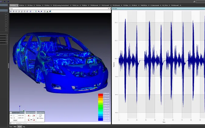
- Flexible subframe. A flexible part enters the multibody model as a reduced finite element model: interface nodes carry the loads, a few modes carry its own deformation. After the run the modal coordinates are expanded to stress.
- Durability and comfort. The same run returns interface force histories for stress and fatigue damage, and seat and steering wheel acceleration for comfort, so a design change is judged on both at once.
Which tyre and road model do ride, handling and durability each need?
The tyre is where most vehicle models are won or lost. Handling is governed by slip: the forces at the contact patch as functions of slip angle, slip ratio, vertical load and camber. Empirical curve fits such as the Magic Formula, set out in Pacejka's Tire and Vehicle Dynamics, reproduce these well for steady manoeuvres and, with a relaxation length, for transient ones. They are fits to tests, not a physical tyre, so they hold only inside the measured range. Ride and durability ask for something else. The tyre must envelop kerbs, joints and potholes and carry belt dynamics at higher frequency, so a flexible-belt or finite-element-derived tyre model on a three-dimensional road is the right tool. A handling tyre on a rough road gives smooth, wrong loads. For water on the patch, see our tyre hydroplaning simulation article.
The road is data. ISO 8608 specifies how measured vertical road profile data are reported, for roads and for off-road terrain, so that profiles from different sources can be compared; it does not say how to measure. We work from your measured routes and, where only a road class is known, generate profiles with matching statistics, and check the profile against measurement before it produces loads.
How do virtual road loads reach durability and comfort?
Run the model over the road and every connection reports a force history: at the wheel centre, at each bush and damper mount, at the subframe attachments. Those histories are the virtual road loads. For a stiff part they pass to a stress model as load cases. For a part whose own flexibility matters, a subframe, a control arm, a knuckle, an anti-roll bar, and the body for ride, the part enters the multibody model as a reduced finite element model. In the method of Craig and Bampton (AIAA Journal, 1968) the part is described by its interface displacements, the constraint modes, plus a small set of fixed-interface normal modes. After the run, the modal coordinates are expanded back to stress over the full mesh. The same model that decides ride then supplies the loads that decide fatigue.
Durability follows: stress histories from unit-load or modal superposition, cycle counting and damage per route, as set out on our durability and fatigue life page. Comfort comes from the same run: acceleration at the seat rail, floor and steering wheel, weighted for human response, with ISO 2631-1 as the standard for evaluating human exposure to whole-body vibration. A damper change is judged on ride and on the load it sends into the subframe at once.
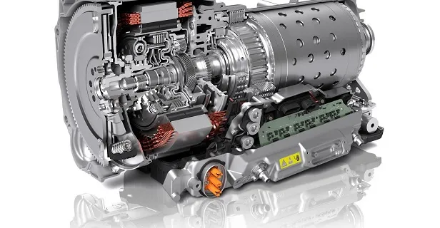
Driveline loads come from the same vehicle. A torque step at tip-in winds the shafts, takes up backlash and sends peak loads into half-shafts, mounts and subframe, events a smooth-road campaign may never contain.
Where does a vehicle model usually go wrong?
- Component data from static tests. A bush given one stiffness, though rubber stiffens with frequency and amplitude.
- Everything rigid. A flexible subframe or body mode near wheel hop or an engine order moves loads and vibration that a rigid model cannot show.
- Correlation at one point. Kinematics match on the rig, yet dynamic wheel forces on the road do not, because damper, stop or tyre was never checked there.
- Peaks instead of damage. A history that matches in peak force but not in frequency content gives the wrong fatigue life.
- A model that lives in one analyst's files. Each variant is rebuilt by hand.
How is a vehicle model verified and validated?
Verification comes first and is cheap. We sweep the suspension to confirm that the kinematics match the hardpoints, check constraint violation and energy drift, and repeat the run with a smaller step, which matters with stiff bushings and bump stops. Validation climbs in layers: component tests of bushes, dampers, springs and tyres; a kinematics and compliance rig; and road data from wheel force transducers and accelerometers, compared in time and frequency, with damage as the final measure. Agreement criteria are written down before the comparison. Rubber, dampers and tyres scatter from part to part and with temperature, so a planned set of cases gives a band of loads, and a design is judged against its upper edge.
| Question | Vehicle model | Tyre and road | Flexible parts |
|---|---|---|---|
| Ride over rough roads, seat vibration | Full vehicle, nonlinear bushes, dampers, stops | Enveloping tyre, 3D road | Body and subframe modes near the excitation |
| Handling and stability | Full vehicle with steering compliance | Slip-based tyre with relaxation, flat road | Steering and subframe compliance |
| Fatigue loads for a subframe or bracket | The ride model over each durability route | Enveloping tyre, 3D road from your routes | Reduced FE model of the part, stress recovery |
| Driveline shock, tip-in, clunk | Driveline and mounts on a full vehicle | Longitudinal slip tyre | Shafts and housings where torsion matters |
| Early hardpoint and spring choices | Reduced model or surrogate with stated range | Simple tyre, representative road | None until the shortlist is small |
A model validated for handling is not validated for loads
- Road spectrum. Road roughness has more energy at long wavelengths than at short ones, so on a vehicle at speed the low-frequency end drives the body and the high-frequency end drives the wheel and the structure.
- Body bounce. The sprung mass moving on its spring and damper gives a low-frequency resonance. Damping controls its height; the spring rate sets where it sits.
- Wheel hop. The unsprung mass on the tyre stiffness gives a second, higher resonance, with the damper acting between them. Both resonances appear in a rigid-body quarter-car model.
- Flexible body mode. A subframe or body mode adds a resonance that no rigid-body model contains. It matters for ride and for the loads in that part when it lies near an excitation such as wheel hop or an engine order.
- Damper trade-off. A stiffer damper lowers the body-bounce peak but raises the response in the isolation region above it, which is the harshness the occupant feels. Tuning is a compromise, not a single optimum.
- Where a rigid model is blind. Above the first structural modes the rigid-body curve and the real vehicle part ways. Loads and vibration there need the flexible parts in the model.
Where does AI help vehicle dynamics simulation, and where does it not?
- A surrogate of load channels and ride metrics over hardpoints, bush rates, damper curves and mass cases, trained on a planned set of multibody runs, so a trade study over many variants becomes affordable. See surrogate models for CFD and FEA.
- Identification of component models from rig data: bush and damper behaviour fitted to measurements, with parameter uncertainty.
- Road and load reconstruction: estimating the road input or an unmeasured load from measured channels, an inverse problem checked against held-back channels.
- Optimisation with a validated surrogate in the loop, trading ride, handling and component load, with finalists confirmed in the full model. See AI surrogate models you can sign off.
Where it does not help: replacing the multibody solver for a topology it has not seen, or standing in for the contact events, a bump stop or a kerb strike, that set the peak loads. A surrogate trained on one chassis family does not know the next. It carries a stated range, and requests outside it go back to the solver.
From one load-case study to a vehicle model your team keeps
The return comes when the next variant, a heavier battery or a new tyre supplier, is a parameter change and an automated run, checked the same way every time.
- Physics model. CFD and FEA set up once, as templates: geometry clean-up, mesh, solver settings and post-processing that every later run reuses.
- Validation. Mesh and time-step studies, and comparison with tests or full-scale data, so the model's uncertainty is known before it is trusted.
- Automated runs. Scripted runs over the parameters and operating conditions that matter, on your hardware or in the cloud.
- AI surrogate. A machine-learning model trained on those runs answers in seconds and says how sure it is; low-confidence questions go back to the solver.
- Decision tool. Optimisation, trade-off charts or operating guidance, in a form your engineers and operators use every day.
- Field data. Test, trial and monitoring data flow back to recalibrate the model, so it improves with every project instead of being rebuilt.
- A parametric vehicle template in your existing solver, Simpack, MSC Adams or the Ansys and Abaqus toolchain for the flexible parts: hardpoints, bush and damper curves, mass cases, tyre and road as parameters.
- An event library: your ride routes, manoeuvres and driveline events, each with the same scripted report.
- A scripted load hand-off: interface forces and modal coordinates exported to the stress and fatigue templates, with a transfer check.
- A correlation record: component, rig and road data for each vehicle, with the agreement measure for each channel written down.
- A surrogate with a stated range for load channels and ride metrics over the design parameters, with a gate that sends out-of-range requests to the full model.
- Handover and training, so your engineers extend it themselves. See our training and software development services.
Questions engineers ask about vehicle dynamics simulation
What is vehicle dynamics simulation used for?
Can virtual road loads replace proving-ground testing?
Do I need flexible bodies in a full-vehicle model?
How accurate is a vehicle multibody simulation?
Which solver do you work with?
If a vehicle programme is on your desk, send us the suspension hardpoints or a CAD export, the bush, damper, spring and tyre data you hold, and one measured ride or road-load record with its route, together with the decision it is meant to support. We will reply with how we would build and check the model, which comparison we would run first, and what the first set of virtual road loads would let you decide. Start with a conversation. Our vehicle multibody dynamics page and the multibody dynamics section describe the wider capability.