Why stamping simulation misses springback, and how die compensation closes the loop
With high-strength steel and aluminium, the die surface that gives the right part is not the part geometry. Why simulation misses springback, what a forming limit curve cannot see, how coil scatter breaks a compensated die, and a gated loop that gets to the drawing in fewer try-outs.
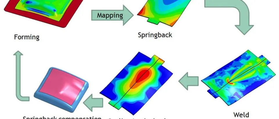
Springback compensation means reshaping the die so that the part, once it leaves the tool and relaxes elastically, lands on the drawing. Stamping simulation can drive that reliably only when the material model captures unloading and the predicted deviation has first been checked against a scanned part.
The first-off part is clamped in the checking fixture and a flange lifts off the gauge at one corner. The die goes back to the machine shop, comes back, and the part is measured again. With advanced high-strength steels (AHSS) and aluminium the surface that gives the right part is not the part geometry, and each trip around that loop costs try-out time, press time and, in the end, the launch date. Our sheet metal forming simulation page describes the capability; this article explains why predictions miss, how to gate a compensation loop, and what to keep.
Why does a stamped part spring back, and why is it worse with AHSS and aluminium?
Forming bends and unbends the sheet over die radii and draw beads, so the outer and inner fibres go past yield while the middle stays elastic. When the tool opens, the sheet takes the opposite moment elastically. For a wide sheet the curvature changes by Δκ = −M/D, where M = ∫σ z dz is the bending moment the loaded stress profile carried and D = E t³ / 12(1 − ν²) is the bending stiffness of the sheet. What stays behind is a layered residual stress, which is why a part keeps moving when it is trimmed, flanged or clamped.
Two levers follow. Higher strength raises σ and so M: in the textbook case of elastic, perfectly plastic pure bending the recovered fraction of curvature depends on a single group, Rσy/(E t), with R the bend radius and t the thickness, so AHSS recovers more than mild steel at the same radius. A lower modulus lowers D: aluminium alloys have roughly a third of the modulus of steel and recover more at comparable strength. Sidewall curl and twist come from the stress difference that builds up as the sheet runs over radii and beads.
- Plastic loading. Drawing over a die radius and a bead takes the metal past yield and hardens it. The curve you calibrated from a uniaxial test describes this part of the loop well.
- Unloading is not at the textbook modulus. After plastic strain the slope on unloading is lower than the initial Young modulus, so more strain is recovered than a constant-modulus model predicts.
- Bauschinger effect. When the sign of the stress reverses, as when sheet is bent and unbent over a die radius or through a draw bead, the real metal yields early. Isotropic hardening yields late and gets the stress in the sidewall wrong.
- Stress through the thickness, loaded. In a bend the outer fibre is in tension and the inner fibre in compression, with an elastic core around the mid-surface.
- Release. Lifting the tool applies the opposite moment, which the sheet takes elastically. The profile is linear, and its size is set by the moment M = ∫σ z dz that the loaded profile carried.
- Residual stress. Loaded plus release leaves a layered, self-balanced stress. It is why a part keeps moving when it is trimmed, flanged or clamped into a fixture.
- Integration points. A shell element samples the profile at a few points through the thickness. Too few and the moment M is mis-integrated; the error does not shrink smoothly, so a small change in set-up can flip the answer.
- Curvature change. The released moment changes curvature by Δκ = −M / D, with plate stiffness D = E t³ / 12(1−ν²). Higher strength raises M; a lower modulus, as in aluminium, lowers D.
Why does simulation not predict springback?
Springback is a small difference between large, opposite stresses, so every modelling approximation in forming is amplified when the tool opens. The usual gaps are below, each with the check that closes it.
| Model choice | What it gets wrong | What we check or change |
|---|---|---|
| Yield criterion: Hill'48 or a Barlat-type function such as Barlat and co-workers' Yld2000-2d (2003) | A quadratic surface has few anisotropy parameters; Yld2000-2d was formulated for aluminium sheets and has more | Uniaxial tests at several angles, a biaxial test |
| Hardening: isotropic or combined (for example Yoshida-Uemori) | Isotropic hardening yields late after reversal; sheet yields early (Bauschinger effect), as in the bend-unbend path over a radius | Cyclic tension-compression or bending data |
| Unloading modulus | A constant modulus under-predicts recovery; Yoshida, Uemori and Fujiwara (2002) report that Young's modulus decreases as prestrain increases | Unloading slopes; modulus as a function of plastic strain |
| Shell integration points | Too few points mis-integrate the moment; Wagoner and Li, “Simulation of springback: Through-thickness integration” (2007) show the error oscillates and give guidelines tied to the error you accept | Integration-point convergence study for the release |
| Contact and friction | One constant coefficient ignores pressure, speed and lubricant; sidewall stress, and so curl, depends on it | Strip-draw or draw-bead tests, measured draw-in |
| Mesh and time integration | Elements too coarse for the tool radius misrepresent curvature and bending strain | Refine at radii; release static and implicit |
These errors compound. Cleveland and Ghosh, “Inelastic effects on springback in metals” (2002) showed that inelastic strain release can be a major source of recovery beyond elastic unloading, so a model that assumes purely elastic unloading can under-predict. Our article on crash models you can trust makes the same point about material cards.
Validate the prediction on an uncompensated part before you cut the die
What does a forming limit curve tell you, and what does it miss?
A forming limit curve (FLC) plots the limiting major strain against the minor strain at which a sheet starts to neck locally. Simulation compares the strain in each element with the curve to give a margin to failure. ISO 12004-2:2021, Metallic materials, Determination of forming-limit curves for sheet and strip, Part 2: Determination of forming-limit curves in the laboratory sets the laboratory conditions for constructing one: ambient temperature, linear strain paths and flat metallic material between 0.3 mm and 4 mm thick.
Three things fall outside it. First, real parts do not strain along straight lines: a sheet bent over a radius and then stretched follows a non-linear path, and a curve measured on linear paths misjudges it. Criteria that do not depend on the strain path exist, and they need their own calibration. Second, an FLC is measured with intact edges, while a flange stretches a cut edge. Edge cracking is why a separate test exists: ISO 16630, Metallic materials, Sheet and strip, Hole expanding test determines the hole expansion ratio and is used to assess whether a product is suitable for forming flanges. Third, an FLC describes necking in stretching; cracks that start at the outer surface of a tight bend or in shear need a fracture model and the test that feeds it.
Why does a compensated die still miss when the coil changes?
A compensation is tuned to one set of conditions: one coil's strength and thickness, one lubricant film, one binder force, one press. Between coils those move, and so does springback. The robustness question is whether the spread of the deviation fits inside the tolerance band. We answer it by running the validated model over the measured spread of the inputs, taken from incoming tests and press settings, and reporting which input drives the deviation. If the spread alone exceeds the band, no die surface fixes it. The remedy is in the process: stiffening features, a restrike, a tighter incoming property window or binder control. A study this size is more solver runs than anyone queues by hand, which is where a surrogate earns its place.
How does die compensation work, and where does it stop converging?
The idea is simple: move the die surface opposite to the predicted error and repeat until the part meets the target. Gan and Wagoner, “Die design method for sheet springback” (2004) present such a displacement-adjustment method for general dies, in which nodal displacement vectors adjust a trial die iteratively until the target shape is reached. The same inverse idea drives pre-compensation in metal additive manufacturing. What makes it work in a press shop is the gating around it. We iterate virtually first, until the predicted part meets the target, and cut the die to the compensated surface only then. Try-out starts closer to the drawing, and it tests the model as well as the tool.
- Target. The part geometry and its tolerance, with the same datum scheme the checking fixture and the scan will use.
- Simulate. Forming, trim and release with the validated material card and the templated set-up. Forming is usually run explicitly and the release statically.
- Deviation. Predicted shape minus target at the gauge points that matter, with the sign kept: it is the field you will invert.
- Gate A: does the model reproduce the part? Before any steel is cut, the predicted deviation of the uncompensated tool is compared with the scan of a real first-off part. If the pattern or size disagrees, fix the model first.
- Compensate. Move the die surface by the opposite of the deviation, scaled by a relaxation factor k, smooth it, and check that it can be machined. Re-run the formability check, because over-bending changes the strain.
- Try-out and scan. Hit the compensated tool, scan the part and align it exactly as the simulation was aligned, so a datum difference is not read as springback.
- Gate B: converged? If the deviation is inside tolerance and the spread is acceptable, release the die with its record. If not, feed the scan back and repeat; stop if two passes do not improve it, because then the cause is the model or the process.
- Coil-to-coil spread. Property, thickness, friction and press scatter move the deviation from part to part. A compensated die only helps if that spread fits inside the tolerance band.
The loop stops converging for reasons worth knowing in advance:
- The model was not validated (gate A): compensating a wrong prediction moves the error.
- The surface cannot be made. A compensated surface must be smooth and machinable, with trim lines and undercuts respected.
- Over-bending changes the strain, so the formability check against the FLC is repeated on every pass.
- The deviation does not shrink between passes. A relaxation factor below one stabilises the loop; if two passes still do not improve it, the cause is scatter, a missing mechanism or a part that needs a process change.
Where does AI/ML help in sheet metal forming, and where does it not?
AI/ML earns its place around the solver; the solver and the scan stay the gate.
| Use | What it does | Limit |
|---|---|---|
| Calibrating material cards from a handful of tests, with uncertainty | Fits yield, hardening and unloading parameters to uniaxial, cyclic and bending data together; returns ranges, not single values | Untested parameters stay unidentified; a wrong model form is not rescued by a good fit |
| Surrogate of deviation against process and material parameters | Predicts gauge-point deviation from strength, thickness, friction and binder force, trained on planned solver runs | Valid only in the sampled ranges and geometry; inherits solver error |
| Automated compensation loop with a convergence gate | Scripts morph, re-simulation and comparison, and applies the stop rule; automation more than learning | No better than gate A and its manufacturability rules |
| Anomaly gate on measured scans | Compares each scan with the prediction, reduced to shape modes, and flags deviation outside the band of earlier parts: new coil, lubricant, die wear, model problem | Flags, does not diagnose; needs a history of good parts |
Where it does not help: a network trained on past parts knows nothing about a new geometry or alloy, and none repairs a card that lacks the Bauschinger effect or the unloading modulus. We keep the constitutive physics in the solver. For the method, see our articles on surrogate models for CFD and FEA and validating AI surrogates, and our pages on surrogate modelling, uncertainty quantification and validation and benchmarking.
From one die try-out to a springback workflow you keep
A single compensation answers the part it was run for. The larger return comes when material cards, set-up and scan comparison become something your engineers run for every new part, so the next die starts from a validated template. We build springback and formability work this way: consulting to diagnose, custom workflow tools and surrogates to build, training to hand over.
- Physics model. CFD and FEA set up once, as templates: geometry clean-up, mesh, solver settings and post-processing that every later run reuses.
- Validation. Mesh and time-step studies, and comparison with tests or full-scale data, so the model's uncertainty is known before it is trusted.
- Automated runs. Scripted runs over the parameters and operating conditions that matter, on your hardware or in the cloud.
- AI surrogate. A machine-learning model trained on those runs answers in seconds and says how sure it is; low-confidence questions go back to the solver.
- Decision tool. Optimisation, trade-off charts or operating guidance, in a form your engineers and operators use every day.
- Field data. Test, trial and monitoring data flow back to recalibrate the model, so it improves with every project instead of being rebuilt.
- A validated material-card library: each grade and supplier, the tests behind its card and its stated uncertainty.
- A templated simulation set-up: the same mesh, integration and release rules for every part, so results compare across dies.
- Measurement-to-model comparison: scans aligned on your datums and compared with the prediction, with the gate that says whether the model is trusted.
- Compensation automation: morphing, re-simulation and the convergence gate scripted around your existing forming solver.
- A trained surrogate with a stated validity range for coil-to-coil robustness, with a route back to the solver outside it.
- Handover and training, so your engineers extend the workflow themselves. See our training and software development services.
Questions engineers ask about springback compensation
Why does my simulation under-predict springback?
Is implicit or explicit better for springback?
How many compensation iterations are normal?
Can a forming limit curve predict edge cracking?
Which software do you use?
If a die is stuck in try-out, send us one part number with its CAD and tolerance, the material card and coil certificates you used, the tool geometry or the compensation history, and a scan of the first-off part. You get a written diagnosis of which of the gaps above explains the deviation, a short test plan to close them, and a plan for the workflow. Our sheet metal forming work sits inside metal forming simulation and beside our consulting service, and the place to start is a conversation.