Passenger thermal comfort and HVAC design with CFD, before the first prototype
Draughts, cold feet, a hot head and a fogged windscreen are found in the climatic chamber, after the vents and seats are frozen, while the HVAC competes with the traction battery. How CFD, comfort models and AI move that conversation into design.
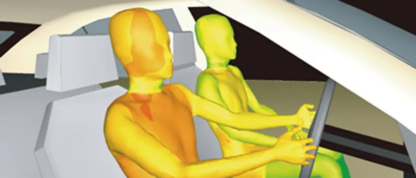
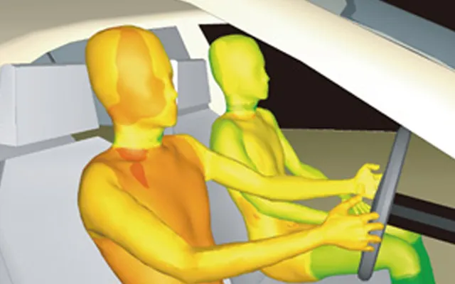
Thermal comfort CFD predicts the air speed, temperature, humidity and radiation each occupant feels, from the cabin's HVAC layout, glazing and solar load, then converts those fields into comfort indices while the design can still change. It replaces a hope that vents, ducts and seats frozen last quarter will feel right in the climatic chamber this winter.
In an electrified vehicle the cabin competes with the drive for the same battery. A 2015 NREL paper, Climate Control Load Reduction Strategies for Electric Drive Vehicles in Warm Weather, states that passenger compartment climate control is one of the largest auxiliary loads on a vehicle. Comfort cannot be bought by running the HVAC harder, because the energy comes out of range. The complaints never change: a draught on the neck, cold feet under a hot head, a windscreen that fogs on the first cold morning or clears too slowly. Mock-ups and climatic chambers find them, but late, on tooled hardware, when the remaining fixes are a software calibration or a bigger HVAC unit. The vents, ducts, seats and glazing were decided long before a prototype existed. The same trade runs through trains, aircraft, eVTOL cabins, and buildings. Our passenger thermal comfort and vehicle thermal management pages describe that work.
What is thermal comfort CFD, and how does it work for a cabin?
Start with the heat balance, because the airflow only distributes it. The HVAC must remove or supply what the cabin gains: QHVAC = Qsol + Qcond + Qvent + Qocc − C dT/dt. Solar load enters through the glazing. Conduction crosses the body panels and glass. Ventilation brings in the enthalpy of outside air. Occupants add metabolic heat. The last term is the heat stored in trim, seats and glass, which a hot-soaked or cold-soaked cabin gives back for minutes, so it never starts a drive in steady state. A lumped balance sizes the unit but cannot say where the heat lands.
- Solar load through glazing. Short-wave radiation passes the glass and is absorbed by the dashboard and seat, which re-emit it as long-wave heat. Glass type, angle and trim colour set how much arrives and where.
- Glazing and the radiant field. Glass is a surface at its own temperature: cold in winter, hot in sun. The occupant feels it by radiation, and moist air condenses on it whenever its surface falls below the local dew point.
- Vent jets. Dashboard, defrost and footwell jets carry momentum into the cabin. Their throw, entrainment and mixing with room air decide whether they reach the face, the chest or the legs, and whether they are felt as a draught.
- Occupant plume. Each person is a heat source with a rising thermal plume. In a small cabin it competes with the jets, and the Richardson number says which wins.
- Comfort zones. Head, torso and feet are judged separately. A warm head and cold feet can sit together at an acceptable average temperature, which is why one cabin number hides the complaint.
- Fresh air and recirculation. Outside air carries an enthalpy load, recirculated air does not, but recirculation raises humidity and the fogging risk. The mix is a comfort decision as much as an energy one.
- Seat contact and trim mass. Seat surfaces touch the body directly, and trim, glass and the shell store heat, so a cabin never reaches steady state at the start of a drive.
CFD resolves that, solving air flow, heat and moisture around real seats, outlets and glass, with conduction in the solids coupled in. Its output is not a verdict but fields at each body segment, which a comfort model must interpret.
Why is cabin airflow so hard to predict?
Because buoyancy and momentum are of the same order. The Richardson number, Ri = gβΔT·L/U² (the same group appears as the Archimedes number), compares them. A dashboard jet is forced convection, an occupant's plume and a sun-heated surface are buoyant, and the two meet within tens of centimetres. Where Ri is small the jets dominate, where it is large the plumes do, and near unity a small change of vent angle can flip the flow pattern. So use the measured outlet flow, direction and temperature as boundary conditions, not the nominal ones.
Three modelling choices then decide whether the fields can be trusted. Turbulence: steady RANS models suit layout sweeps, but smear the unsteady jet and plume interaction behind many draught complaints, which LES or hybrid models can resolve at higher cost. Near-wall treatment: skin heat loss depends on the boundary layer, so verify it. Radiation: a body exchanges heat with glass, roof and seat by radiation as well as with the air, so long-wave surface-to-surface exchange belongs in the model, and the sun needs ray tracing through glass with real transmission and trim absorption, not a uniform flux on the roof.
| Choice | Adequate for | Misleads when |
|---|---|---|
| Steady RANS | Vent-layout sweeps and mean zone temperature and velocity | Jet and plume interact unsteadily and the pattern flips |
| LES or hybrid | Draught complaints and plume interaction on shortlisted designs | Used for sweeps, where the cost cannot be paid |
| Surface-to-surface radiation | Radiant asymmetry from glass, roof and seat | Left out, so a cold window feels like warm trim |
| Conjugate solids | Glass, trim and seat temperatures over a warm-up or pull-down | Trim mass and properties are uncalibrated |
How is window fogging and defrost simulated?
Fogging is a humidity problem. Breath and damp clothing add moisture, and vapour condenses wherever a surface is below the dew point of the air touching it. The model carries water vapour as a transported species, couples it to a glass temperature from a conjugate model, and monitors the margin between glass temperature and local dew point across the windscreen. Defrost adds heat conduction through the glass and a melting front driven by the warm jet along the screen, which is inherently transient. In the US, FMVSS No. 103 specifies requirements for windshield defrosting and defogging systems, a test you will eventually run in a chamber. Simulation tells you earlier whether the outlet geometry has a chance, and exposes a trade energy teams want to make: recirculating air saves HVAC energy but raises humidity at the glass you need clear.
Can PMV and PPD predict comfort in a car?
Only inside the range they were built for. ISO 7730 covers the analytical determination of thermal comfort using the predicted mean vote (PMV), the predicted percentage of dissatisfied (PPD) and local thermal comfort criteria, for healthy adults in moderate indoor environments. ASHRAE Standard 55 works from the same six factors: air temperature, radiant temperature, humidity, air speed, activity and clothing. Berkeley's CBE Thermal Comfort Tool implements it and notes that the standard applies only to healthy individuals. PMV is a whole-body, steady-state vote. A cabin is neither uniform nor steady.
The vehicle-specific part, ISO 14505-2, is titled "Determination of equivalent temperature" and gives guidelines for assessing thermal conditions inside a vehicle compartment. Its scope also says it is primarily intended for assessment when deviations from thermal neutrality are relatively small, and that its methods can be chosen for HVAC performance tests. Even the vehicle standard therefore marks a boundary: a cabin after a hot soak or a cold start is not a small deviation. Multi-segment physiology models go beyond it: Fiala, Lomas and Stohrer (1999) in the Journal of Applied Physiology modelled the passive heat transfer of the human body, and Zhang et al. (2010) in Building and Environment published sensation and comfort models for non-uniform and transient environments. They target the conditions PMV cannot cover but, like any empirical model, have a calibration range that matters.
| Measure | Needs from the CFD | Good for | Limit |
|---|---|---|---|
| PMV and PPD (ISO 7730) | Zone air and radiant temperature, speed, humidity | Near-steady comparison of design variants | Whole-body, steady; blind to local asymmetry |
| Equivalent temperature (ISO 14505-2) | Segment heat loss from a manikin or from simulation | Vehicle HVAC assessment by body segment | Small deviations from neutrality only |
| Multi-segment physiology models | Time histories of temperature, speed and radiation at each segment | Warm-up, pull-down, non-uniform exposure | Needs clothing, seat-contact and calibration inputs |
A comfort index models people; it is not a property of the air
How do you validate cabin CFD against manikin and chamber tests?
Link by link, because errors cancel. First the boundary conditions: measured vent flow, direction and temperature, glass and trim temperatures, solar lamp irradiance. Then the field: air temperature and speed at probes near head, chest, knees and feet. Then the body surface: segment heat loss of a thermal manikin, or equivalent temperature. Last, the votes of people. A model matching the manikin but not the field is right for the wrong reason. A single chamber run is also one realisation, with its own scatter, which we state beside the model error.
Drive-cycle transients add the time dimension. Resolving a whole warm-up in CFD is expensive, so the practical split is a 0D/1D model of cabin, HVAC and battery over the cycle, as in our EV thermal management simulation article, with CFD run at chosen snapshots: the cold start, a few minutes in, and the settled state. The CFD returns zone data that calibrate the fast model.
- Inputs. Ambient temperature, solar load, vent flow and temperature, occupancy, clothing and the drive cycle. Most of the uncertainty in a comfort prediction enters here.
- CFD field. Air temperature, velocity and humidity in the cabin, with glass and trim surface temperatures and radiation. Turbulence, radiation and wall treatment are the choices that matter.
- Body model. A heat balance for each body segment through skin and clothing, from a thermal-manikin style calculation up to a multi-segment physiology model.
- Comfort index. Equivalent temperature, local sensation or an overall vote such as PMV. Each was built for a stated range of conditions, and a cold-start cabin can lie outside it.
- Decision. A vent position, a flow, a set point or a control rule. The change goes back into the inputs for the next run, so the loop keeps closing.
- Chamber and manikin data. Measured boundary conditions, glass temperatures and segment heat loss check the field, the body model and the index in turn.
- Surrogate with a trust gate. A trained model goes straight from inputs to indices for fast studies. Cases outside its training range go back to the solver.
Where does AI help thermal comfort and HVAC design, and where does it not?
- Surrogates of cabin fields and indices, trained on a planned set of CFD runs over vent position, angle and area, flow, supply temperature, ambient and solar case, predicting zone temperatures, segment air speed and comfort indices in seconds. See surrogate models for CFD and FEA.
- Energy versus comfort studies. A fast cabin model, calibrated on CFD and chamber data, runs pre-conditioning, recirculation and zonal or seat heating strategies over drive cycles and shows segment comfort against HVAC energy before the controller is frozen.
- Calibration from chamber data: inferring trim thermal mass, contact resistance, glass properties and clothing insulation, the inputs that are hard to know. See hybrid physics and AI modelling.
- Vent-layout optimisation with a draught limit and a fogging margin as hard constraints. See generative design and optimisation.
- A solver gate that sends any request outside the training range back to the CFD.
The limits are real. A surrogate interpolates: a new cabin shape, a new outlet type or a condition beyond its training set returns a confident wrong answer unless it is gated. It also inherits the fidelity of what it was trained on, so a surrogate of PMV is a fast copy of PMV, limits included. It does not replace validation. See validation and uncertainty for AI surrogates and our validation and benchmarking work. For the seat itself, see seat thermal comfort.
From one cabin study to a comfort capability you keep
A single study answers the question it was asked. The larger return comes when the set-up becomes a workflow your team runs, so the next vent layout, glazing option or control strategy costs hours, not weeks, and every answer is checked the same way. That is how we build thermal comfort work.
- Physics model. CFD and FEA set up once, as templates: geometry clean-up, mesh, solver settings and post-processing that every later run reuses.
- Validation. Mesh and time-step studies, and comparison with tests or full-scale data, so the model's uncertainty is known before it is trusted.
- Automated runs. Scripted runs over the parameters and operating conditions that matter, on your hardware or in the cloud.
- AI surrogate. A machine-learning model trained on those runs answers in seconds and says how sure it is; low-confidence questions go back to the solver.
- Decision tool. Optimisation, trade-off charts or operating guidance, in a form your engineers and operators use every day.
- Field data. Test, trial and monitoring data flow back to recalibrate the model, so it improves with every project instead of being rebuilt.
- A parametric cabin template. Vent, seat and glazing variants, occupant and solar set-up, meshing and segment-level post-processing.
- A validation record tying the model to your chamber and manikin tests, with a stated uncertainty for each link.
- Automated runs over ambient and solar cases, flow rate, supply temperature and geometry.
- A fast model or surrogate of zone temperatures, velocities and indices, with its training range written down and a gate that sends everything else back to the solver.
- A control-strategy study tool trading segment comfort against HVAC energy over your drive cycles.
- Training and handover, so your engineers can extend the workflow themselves. See our training and software development services.
Questions engineers ask about cabin thermal comfort simulation
What is thermal comfort CFD?
Is PMV good enough for a vehicle cabin?
How accurate is cabin CFD?
Can AI replace climatic chamber tests?
What do you need from us to start?
Our CFD consulting and AI/ML integration services cover this ground, within the thermal analysis work we do. If a vent layout, a glazing choice or a comfort-versus-range trade is on your desk, send us the geometry, the boundary conditions you can measure and the complaint you want to remove. We will reply with how we would build the model, which test data would validate it, and what the first results would decide. Start with a conversation.