Tyre hydroplaning simulation: how CFD and FEA predict the speed at which grip is lost
Hydroplaning is a fluid–structure problem in a contact patch the size of a postcard. How coupled simulation predicts it, why tread, load and wear matter, and how AI balances wet safety against noise and rolling resistance.
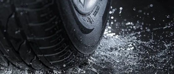
Hydroplaning simulation predicts the moment a tyre stops touching the road and starts riding on water. Above a critical speed, water ahead of the tyre cannot escape fast enough. It builds a pressure wedge that lifts the tread, the contact patch shrinks, and braking, steering and stability go with it.
For tyre makers it is one corner of a demanding trade-off with rolling resistance, noise and wear. For vehicle makers it is a safety question that changes with vehicle mass, load distribution, tyre size and inflation pressure. In the EU, the wet grip class on every tyre label comes from a standard braking test, under the EU tyre labelling regulation (EU) 2020/740. Aquaplaning is a separate behaviour that wet-grip ratings do not fully capture, which is why it is studied in its own right.
The physics under a wet tyre
A rolling tyre meets the water film with the speed of the vehicle. The water stagnates against the front of the tyre, and its dynamic pressure, roughly ½ρV2, grows with the square of speed. At motorway speeds that pressure becomes of the same order as the tyre's inflation pressure, and the water starts to win.
- Water wedge. Water ahead of the tyre is forced into the contact patch; its pressure grows roughly with the square of speed.
- Squeeze-film zone. At the front of the footprint a thin film still separates tread and road: no useful grip.
- Transition zone. The film breaks down and tread elements start to drape onto the road texture.
- Dry contact zone. Where the tread really grips. It shrinks as speed rises; when it disappears, the tyre is hydroplaning.
- Groove drainage. Grooves and sipes carry water away. Their volume, orientation and wear decide how long the dry zone survives.
The footprint is usually described in three zones. At the front is a squeeze-film zone, where water still separates tread and road. Behind it is a transition zone, where the film breaks down and tread elements drape onto the road texture. At the rear is the dry contact zone that actually provides grip. As speed rises the front zones grow and the dry zone shrinks. When it disappears, the tyre is fully hydroplaning.
Early NASA research on aircraft tyres, summarised in NASA Technical Note D-2056 (1963), gave a well-known rule of thumb. Dynamic hydroplaning speed scales with the square root of inflation pressure: about 9√p knots, with p in psi. The rule captures the physics of the water wedge. Car tyres with deep tread patterns, different footprint shapes and worn grooves depart from it, which is exactly why simulation is needed.
How hydroplaning simulation is done
A credible model has to capture the deforming tyre, the free-surface water flow through the tread and the interaction between them.
| Approach | How it works | Strengths | Limits |
|---|---|---|---|
| Explicit FE with coupled fluid (CEL or ALE) | Tyre and water in one explicit model; fluid on an Eulerian mesh | Robust contact; one code | Fluid resolution limited by cost |
| Particle methods (SPH) | Water as particles interacting with an FE tyre | Natural free surface and splash | Many particles needed for accuracy in grooves |
| Coupled CFD–FEA (FSI) | Volume-of-fluid CFD of the water, FE tyre, coupled each step | Best resolution of groove flow and pressure | Most set-up and computing effort |
| Reduced models | Lift and drag maps from detailed runs, used in vehicle dynamics | Fast enough for full-vehicle manoeuvres | Only as good as the runs behind them |
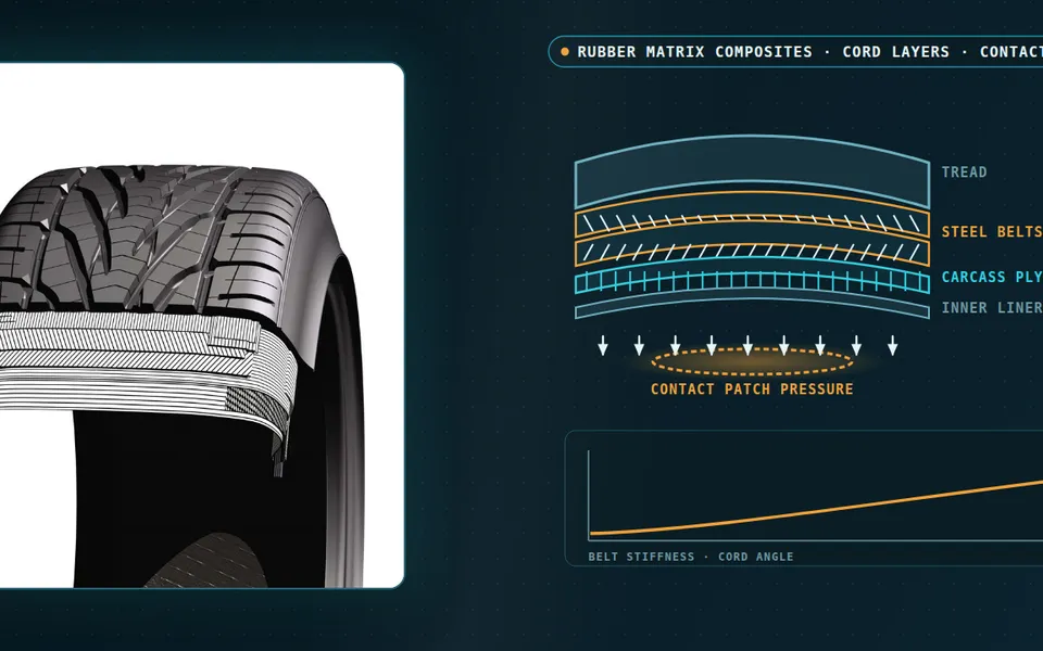
Whichever route is chosen, the tyre model matters as much as the water: rubber hyperelasticity, cord reinforcement, the real tread geometry and the inflation and load state. The outputs are the lift force and contact-patch area against speed, the hydroplaning speed itself, and the forces available for braking and cornering on a wet road. This is one of our fluid–structure interaction specialities.
What changes the hydroplaning speed
- Water depth. Once the film is deeper than the tread can drain, the risk rises sharply.
- Tread pattern and wear. Groove volume, orientation and connection to the shoulder decide how much water is evacuated. Worn tyres lose groove volume and hydroplane earlier.
- Inflation pressure and load. They set the footprint shape and the contact pressure the water has to overcome. A heavier vehicle on the same tyre changes the balance, which matters as vehicle mass grows.
- Footprint shape. A long, narrow footprint drains differently from a short, wide one.
- Manoeuvre. Braking and cornering hydroplaning differ from straight-line running and are where loss of control actually happens.
From tyre to vehicle
Where AI helps tread design
Tread design is a multi-objective problem. Wider, deeper grooves drain water but can increase noise and reduce stiffness; compounds and patterns that lower rolling resistance can cost wet grip. Each coupled hydroplaning run is expensive, so exploring the design space directly is out of reach.
- Surrogates over tread parameters. Groove width, depth, angle and pitch sequence mapped to hydroplaning speed, contact area and lift, trained on a planned set of coupled runs. See our article on surrogate models for CFD and FEA.
- Pareto fronts. The same surrogates, combined with noise and rolling-resistance models, show the trade-off between wet safety and the other targets for a whole family of designs.
- Wear-aware design. Running the surrogate at different wear states shows which patterns keep their wet performance as they wear.
From one study to a capability you keep
A single simulation campaign answers the question it was asked. The larger return comes when the setup becomes a workflow your own team runs. The next variant, loading condition or operating question then costs hours instead of weeks, and every answer is checked the same way. That is how we build tyre and wet-road work.
- Physics model. CFD and FEA set up once, as templates: geometry clean-up, mesh, solver settings and post-processing that every later run reuses.
- Validation. Mesh and time-step studies, and comparison with tests or full-scale data, so the model's uncertainty is known before it is trusted.
- Automated runs. Scripted runs over the parameters and operating conditions that matter, on your hardware or in the cloud.
- AI surrogate. A machine-learning model trained on those runs answers in seconds and says how sure it is; low-confidence questions go back to the solver.
- Decision tool. Optimisation, trade-off charts or operating guidance, in a form your engineers and operators use every day.
- Field data. Test, trial and monitoring data flow back to recalibrate the model, so it improves with every project instead of being rebuilt.
- Templates for geometry, mesh, solver settings and post-processing, documented so results stay consistent from one variant to the next.
- A validation record that ties the simulations to your tests, trials or field data, with the uncertainty stated.
- Automated runs over the parameters and operating conditions that matter, on your hardware or in the cloud.
- A trained surrogate and a simple decision tool, with the limits of its validity written down.
- Training and handover, so your engineers can extend the workflow themselves. See our training and software development services.
Questions about hydroplaning simulation
Is wet grip the same as hydroplaning resistance?
Which method is best?
Can simulation account for tyre wear?
What inputs are needed?
Hydroplaning is part of our hydroplaning and aquaplaning simulation service and of our wider automotive engineering work. If your tyre or vehicle has to stay on the road when it rains, get in touch.