Offshore hydrodynamics for platforms and floating wind: wave loads, motions and mooring fatigue
Every offshore structure is designed against the sea. How Morison's equation, potential flow and CFD each predict wave loads and motions, why floating wind raises the stakes, and how AI handles the design load cases.
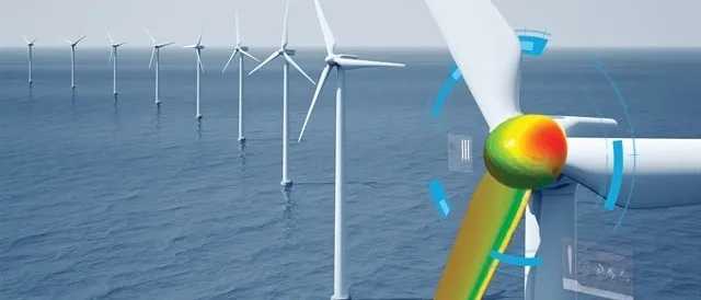
Offshore hydrodynamics is the study of how waves, current and wind load a structure at sea and how it responds. For a fixed jacket it sets the member sizes. For a floating platform it sets the hull, the moorings and the operating limits. For a floating wind turbine it shapes the whole machine, because the rotor, the controller and the floater move together.
The industry is moving into deeper water and new kinds of structure at the same time. Floating wind has its own design requirements, IEC 61400-3-2 and certification standards such as DNV-ST-0119, and design programmes that run thousands of load cases. The models behind those load cases decide whether a design is safe, economical or neither.
The loads on a floating structure
- Waves, current and wind. Irregular sea states described by spectra, current profiles and, for floating wind, the turbulent wind field above.
- Diffraction and radiation. For large-volume hulls, potential-flow panel methods give wave excitation, added mass and radiation damping across frequency.
- Viscous drag and damping. Morison drag on slender members and viscous damping of pontoons and heave plates: where CFD calibrates the simpler models.
- Mooring lines. Line dynamics, seabed contact and tension cycles that set the fatigue life of chain, rope and connectors.
- Second-order drift. Slow-drift and difference-frequency loads that excite the low natural frequencies of the moored system.
- Rotor and controller. For floating wind, aerodynamics, blade elasticity and the pitch controller couple with the platform's motion.
First-order wave loads act at the wave frequencies and drive most of the motion and structural load. Second-order loads act at the sum and difference of wave frequencies. The difference-frequency part drives slow drift of moored structures at their low natural frequencies, where damping is small and responses can be large. Viscous drag, current and, for wind turbines, aerodynamic thrust and the control system complete the picture.
Choosing the right offshore hydrodynamics model
Three families of method cover most offshore work, and their range of validity is set mainly by the size of a member compared with the wave length.
| Model | Applies to | Captures | Misses |
|---|---|---|---|
| Morison's equation | Slender members (diameter small compared with the wave length) | Inertia and viscous drag on jackets, braces, risers and cables | Diffraction around large bodies |
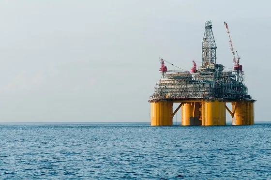
| Potential flow (panel methods) | Large-volume hulls: semi-submersibles, spars, barges, FPSOs | Diffraction, radiation, added mass, radiation damping, second-order drift | Viscous damping and drag |
| CFD (RANS with VOF) | Any geometry, including steep and breaking waves | Viscous damping, slamming, wave run-up, green water, vortex-induced motion | Cost limits it to selected cases |
| Coupled time domain | Floating wind and moored systems | Aero, hydro, servo, elastic and mooring dynamics together | Only as good as the models inside it |
Morison's equation, F = ρCMV u̇ + ½ρCDA u|u|, adds an inertia term and a quadratic drag term per unit length of member, with coefficients from tests or CFD. Panel methods solve the potential-flow problem around the hull for each frequency and heading, giving the transfer functions and quadratic transfer functions (QTFs) that time-domain tools use.
Potential flow is the backbone of offshore design, but it is inviscid. Heave plates, pontoon edges and columns shed vortices that damp motion, and the low-frequency motions of a moored floater are very sensitive to that damping. Studies of floating wind platforms have shown that potential-flow-only models can under-predict some loads and motions near the platform's natural frequencies. The usual remedy is to calibrate drag and damping with CFD or tests, as described in this review of CFD in floating offshore wind turbine design (Haider et al., 2024).
Moorings and fatigue
Mooring lines hold position, and their tension cycles accumulate fatigue in chain, wire, fibre rope and connectors. Quasi-static models treat the line as a sequence of static catenaries. Dynamic lumped-mass or finite element models capture line inertia, drag and seabed contact, which matter for deep water and for fatigue. Fatigue life follows from rainflow counting of tension histories against T–N or S–N curves, summed across the long-term distribution of sea states.
Risers, cables and umbilicals add vortex-induced vibration (VIV) in current, which is a classic case for CFD-calibrated models. Our offshore hydrodynamic FSI work covers these coupled problems.
Why floating wind raises the stakes
A floating wind turbine couples a large, flexible rotor and a pitch controller to a floater with its own dynamics. Platform pitch changes the wind the rotor sees; the controller reacts to that wind and changes the thrust; the thrust moves the platform. A controller tuned for a fixed turbine can make a floating one less stable, so the controller is part of the hydrodynamic design.
- Coupled simulation. Aero-hydro-servo-elastic tools run the whole system in the time domain for each design load case.
- Design load cases. Combinations of wind, waves, current, faults and operating states quickly run into thousands of simulations per design iteration.
- Calibration. CFD of the floater in waves, and of the rotor where needed, calibrates the drag, damping and second-order terms the coupled tools rely on.
Our wind turbine simulation and wind farm work covers the rotor side of this coupling.
Where AI changes offshore hydrodynamics
- Load-case reduction. Surrogates trained on a designed subset of coupled simulations estimate extreme loads and fatigue damage across the full set of design load cases, so the most expensive runs are spent where they decide the design.
- Fatigue surrogates. Damage-equivalent loads at critical locations predicted directly from metocean parameters, for site screening and life-extension studies.
- Design optimisation. Floater geometry, mooring layout and controller settings explored together, with uncertainty quantification on the result.
- Digital twins. Motion, tension and strain monitoring update the model in service, supporting inspection planning and life extension. See digital twins.
From one study to a capability you keep
A single simulation campaign answers the question it was asked. The larger return comes when the setup becomes a workflow your own team runs. The next variant, loading condition or operating question then costs hours instead of weeks, and every answer is checked the same way. That is how we build offshore hydrodynamics work.
- Physics model. CFD and FEA set up once, as templates: geometry clean-up, mesh, solver settings and post-processing that every later run reuses.
- Validation. Mesh and time-step studies, and comparison with tests or full-scale data, so the model's uncertainty is known before it is trusted.
- Automated runs. Scripted runs over the parameters and operating conditions that matter, on your hardware or in the cloud.
- AI surrogate. A machine-learning model trained on those runs answers in seconds and says how sure it is; low-confidence questions go back to the solver.
- Decision tool. Optimisation, trade-off charts or operating guidance, in a form your engineers and operators use every day.
- Field data. Test, trial and monitoring data flow back to recalibrate the model, so it improves with every project instead of being rebuilt.
- Templates for geometry, mesh, solver settings and post-processing, documented so results stay consistent from one variant to the next.
- A validation record that ties the simulations to your tests, trials or field data, with the uncertainty stated.
- Automated runs over the parameters and operating conditions that matter, on your hardware or in the cloud.
- A trained surrogate and a simple decision tool, with the limits of its validity written down.
- Training and handover, so your engineers can extend the workflow themselves. See our training and software development services.
Questions about offshore hydrodynamics
When is Morison's equation not enough?
Is CFD practical for design load cases?
Do you work on fixed and floating structures?
What inputs are needed?
Offshore work spans our structures design including hydrodynamics and energy and power services. For the process side of offshore platforms, see our article on acoustic-induced vibration in piping. If you have a floater, a mooring or a site to assess, start with a conversation.