Acoustic-induced and flow-induced vibration in piping: from AIV screening to CFD–FEA fatigue assessment
High-capacity relief and blowdown systems can crack their own piping. How acoustic-induced vibration (AIV) and flow-induced vibration (FIV) work, how screening finds the lines at risk, and how CFD and FEA turn a warning into a fix.
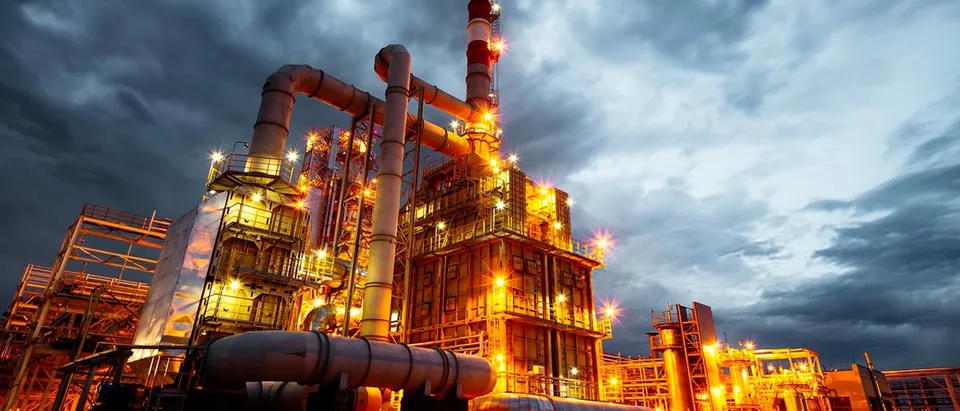
Acoustic induced vibration (AIV) is fatigue damage caused by intense sound inside gas piping. Relief, control and blowdown valves and orifices drop high-pressure gas to low pressure, and in doing so can generate intense acoustic power. That sound vibrates the pipe wall at high frequency and can crack welded connections downstream, sometimes after only short periods of high-flow operation.
Its sibling, flow-induced vibration (FIV), comes from turbulence, vortex shedding, pulsation and slug flow, and acts at lower frequencies on the pipe as a beam. Both are leading causes of fatigue failures in process pipework, and both are far cheaper to design out than to repair on a live plant. Because fatigue cracks at small-bore connections can release hydrocarbons, both are safety issues as well as reliability ones.
How acoustic induced vibration works
Across a pressure-reducing device the gas jet becomes turbulent and, at high pressure ratios, supersonic. The mixing generates broadband sound inside the pipe. That sound travels downstream with little attenuation and excites the circumferential (shell) modes of the pipe wall, typically far above the frequencies of ordinary piping vibration.
- Pressure-letdown source. A relief, control or blowdown valve, or an orifice, with a high pressure ratio and mass flow, generates intense acoustic power.
- Downstream propagation. High-frequency sound travels down the line with little loss, so the risk reaches far beyond the valve.
- Shell-mode vibration. The sound excites circumferential modes of the pipe wall, far above the frequencies of ordinary piping vibration.
- Branch connections. Small-bore branches, welded fittings and supports concentrate stress: this is where fatigue cracks start.
- Screen, then analyse. Likelihood-of-failure screening finds the lines that matter; CFD and FEA then quantify the source, the wall response and the fatigue life.
The wall itself rarely fails in the plain pipe. Fatigue cracks start where the shell vibration meets a stress concentration: small-bore branch connections, welded supports, fittings and other circumferential discontinuities. Thin walls, large diameters and high acoustic power all raise the risk.
The sound power level is commonly estimated with the Carucci–Mueller expression, PWL = 10 log10[(ΔP/P1)3.6 W2 (T/Mw)1.2] + 126.1. It uses the pressure drop across the device, the mass flow W, the upstream temperature T and the gas molecular weight Mw. It came from failure and non-failure experience in the field, and it underpins the screening methods used today.
Screening: the Energy Institute approach
The most widely used reference is the Energy Institute guidelines for the avoidance of vibration induced fatigue failure in process pipework, second edition, 2008. It is cited by design standards including ASME B31.3 and NORSOK L-002, and it is built as a staged process.
| Stage | What is done | Outcome |
|---|---|---|
| Qualitative review | Identify systems with pressure-letdown devices, high flow or multiphase flow | The lines worth screening |
| Quantitative screening | Sound power, pipe geometry and connection type give a likelihood-of-failure (LOF) score | Lines ranked as low, medium or high risk |
| Detailed assessment | CFD of the source and flow, FEA of shell modes and local stresses, fatigue calculation | Confirmed risk and a quantified margin |
| Mitigation | Redesign the source, the pipe or the connections, then reassess | A line that is safe by design |
Screening is deliberately conservative: it is meant to find every line that could be at risk. Its cost is false alarms, and on a large project a handful of high-LOF lines can drive expensive changes. Detailed assessment exists to separate the real risks from the conservative ones.
Detailed assessment with CFD and FEA
For the lines that screening flags, simulation answers two questions: how strong is the source, and how does the wall respond where it matters?
- Source and flow. CFD of the valve or orifice and the downstream piping resolves the jet, the pressure recovery and the turbulence, and checks flow velocities and momentum flux against FIV limits. For FIV, it also shows vortex shedding at dead legs and branches.
- Wall response. FEA of the pipe shell, with the actual branch, fitting and support details, gives the shell-mode frequencies and the local stress at each discontinuity.
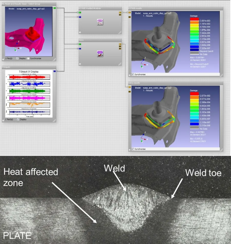
- Fatigue. Local stresses, assessed against weld fatigue classes such as those in BS 7608 or DNV-RP-C203, give a fatigue life rather than a score. Our welded-structure fatigue work uses the same methods.
- Fluid–structure coupling. Where the response feeds back on the flow, a one-way or two-way FSI analysis follows it.
Mitigation that holds up
The best fix depends on whether the problem sits at the source, in the pipe or at a connection.
- At the source: low-noise valve trims, multi-stage pressure reduction or staged opening of relief and blowdown valves lower the acoustic power.
- In the pipe: a thicker wall or a smaller diameter-to-thickness ratio raises the stiffness of the shell modes.
- At connections: full-encirclement reinforcement, contoured fittings in place of small-bore welded branches, and relocating branches away from the highest acoustic power.
- For FIV: supports and bracing that move natural frequencies away from the excitation, and geometry that avoids vortex shedding at dead legs.
Each option has a cost in weight, pressure drop or schedule. Simulation lets a project compare them on the same basis, and reassessing after the change confirms that the risk has actually moved.
Liquid lines and hydroacoustics
Liquid systems have their own versions of the problem: cavitation in control valves and pumps, pressure surges when valves close quickly, and pulsation from reciprocating pumps. The same approach applies: screen the network, then use CFD with cavitation or compressible-liquid models and FEA of the piping where the screening says it matters. Our hydroacoustics and acoustic-induced vibration page covers these services.
Where AI helps with acoustic induced vibration
- Plant-wide screening. Line lists, isometrics and process data are parsed automatically, so screening covers every line and is repeated whenever the design changes.
- Stress surrogates. Models trained on families of FEA runs predict the local stress at common connection types from diameter, wall thickness and acoustic power, so detailed assessment can focus on the unusual cases.
- Monitoring. Vibration measurements on critical lines feed a digital twin that tracks accumulated fatigue in service.
From one study to a capability you keep
A single simulation campaign answers the question it was asked. The larger return comes when the setup becomes a workflow your own team runs. The next variant, loading condition or operating question then costs hours instead of weeks, and every answer is checked the same way. That is how we build piping vibration work.
- Physics model. CFD and FEA set up once, as templates: geometry clean-up, mesh, solver settings and post-processing that every later run reuses.
- Validation. Mesh and time-step studies, and comparison with tests or full-scale data, so the model's uncertainty is known before it is trusted.
- Automated runs. Scripted runs over the parameters and operating conditions that matter, on your hardware or in the cloud.
- AI surrogate. A machine-learning model trained on those runs answers in seconds and says how sure it is; low-confidence questions go back to the solver.
- Decision tool. Optimisation, trade-off charts or operating guidance, in a form your engineers and operators use every day.
- Field data. Test, trial and monitoring data flow back to recalibrate the model, so it improves with every project instead of being rebuilt.
- Templates for geometry, mesh, solver settings and post-processing, documented so results stay consistent from one variant to the next.
- A validation record that ties the simulations to your tests, trials or field data, with the uncertainty stated.
- Automated runs over the parameters and operating conditions that matter, on your hardware or in the cloud.
- A trained surrogate and a simple decision tool, with the limits of its validity written down.
- Training and handover, so your engineers can extend the workflow themselves. See our training and software development services.
Questions about AIV and FIV
What is the difference between AIV and FIV?
When is a detailed assessment needed?
Can AIV be checked on an existing plant?
What do you need to start?
Piping vibration sits between our oil and gas simulation and vibration fatigue work. If a relief or blowdown system has lines flagged high-risk, send us the details.