Aeroelastic analysis for wings, from jig shape and gust loads to the flutter margin
A wing box sized on rigid-wing loads meets the flexible airframe late, in the tunnel or in flight flutter tests. Coupling CFD and FEA on your own solvers finds the flight shape, the gust loads and the flutter margin first, with the scatter of the methods stated.
Aeroelastic analysis couples the aerodynamic load on a flexible wing to its structure, so the flying shape, the wing-box loads and the flutter speed come from one model. We build that chain around your existing CFD and FEA solvers: pressures mapped onto the structural mesh without losing force, deflection fed back into the flow, and gust and flutter cases that run the same way every time.
The wing box is about to go into detailed sizing, and its loads came from a rigid-wing CFD run. Nobody can say what shape the wing flies in at 1g or how near the flexible airframe sits to flutter at the corner of the envelope, and the answer surfaces late: in a flexible-model tunnel entry, a ground vibration test or a flight flutter campaign that must be re-planned. For transport-category airplanes, 14 CFR 25.629 covers flutter, divergence, control reversal and any undue loss of stability from structural deformation, shown by analyses, tests or other means the FAA Administrator finds necessary. Our aerodynamics simulation work already feeds stress analysis; this closes the loop.
What does aeroelastic analysis have to capture on a wing?
Three questions share one coupled model: the shape the wing takes under load and how that changes the load, the dynamic pressure at which a mode stops being damped, and what a gust does to the loads. In modal coordinates the last two read (s2M + sC + K − qAss)η = qAsgwg/U, as Stanford, Thelen and Jacobson (NASA, 2026) write it, with M, C, K from the finite element model, A the aerodynamic matrices, q the dynamic pressure, η the modal amplitudes and wg the gust velocity. Set the right side to zero and flutter is the lowest q at which a root s = σ + iω has σ > 0.
On a typical section the static question has a closed form, and it argues for coupling. For a torsion spring Kθ, area S, lift-curve slope CLα and an aerodynamic centre a distance e ahead of the elastic axis, incidence rises from α0 to α0/(1 − q/qD), where qD = Kθ/(S e CLα) is the divergence dynamic pressure. A rigid run understates the load by that factor.
- Jig shape. The shape the wing is built to, unloaded. It is not the shape in the drawing set, which is the shape under flight load: the structure deflects from one into the other. The CFD model needs the loaded shape, and manufacturing needs the jig shape.
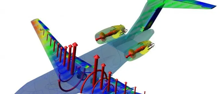
- Aerodynamic load. The CFD pressure on the wing surface, integrated into a distributed lift. On a rigid wing it is computed once. On a flexible wing it is computed on the flexed shape and changes when the shape changes: the two sets of arrows are the first pass on the rigid shape and the converged load.
- Load transfer. The aerodynamic surface mesh is much finer than the structural model, so the nodes never coincide. Forces reach the structural nodes through the transpose of the displacement interpolation, which keeps virtual work, and with it the total force and moment, equal on both sides. The check is an integral of the load before and after the transfer.
- Structural response. The finite element model bends and twists under the nodal forces. Here the converged deflection is larger than the first pass because twist raises incidence and so the load. On a swept-back wing, bending adds nose-down twist and the change can go the other way.
- Displacement transfer. The structural displacements are interpolated onto the aerodynamic surface and the volume mesh is moved with it, keeping cell quality near the wall. The new shape goes back to the flow solver for the next load.
- Section twist and the repeat. A twist of the tip section changes its local angle of attack, so its lift changes. The loop runs until load and shape stop changing; that converged pair is the flight shape, and the jig shape is found by working backwards from the target flight shape.
How do CFD pressures reach the FEA mesh without losing force?
The aerodynamic mesh is fine and the structural model a coarse set of nodes, so the two never match. Displacements pass to the aerodynamic surface through an interpolation ua = H us. Forces return through its transpose, fs = HT fa, which keeps virtual work equal on both sides; if H reproduces rigid translation and rotation exactly, resultant force and moment survive. We integrate the load before and after every mapping and fail the run if either drifts, and hand the loads to the full finite element model for stress.
Jig shape or flight shape: which one is in your CFD model?
The drawing set shows the shape under 1g flight load; the factory builds the jig shape, the unloaded wing that deflects into it. In NASA's Common Research Model test, Rivers, Hunter and Campbell (2012) found the model built to the 1g design shape, not the wind-off shape, so in the tunnel the wing twisted beyond the geometry in the CFD grids; applying the measured twist increment, at most about one degree, improved correlation. The first Aeroelastic Prediction Workshop found the same on a flexible wing: steady pressures needed the static aeroelastic shape, and the rigid shape over-predicted them. We also run the loop backwards, correcting the jig geometry by the computed deflection until the loaded shape matches the target.
How accurate is CFD-based flutter prediction?
The workhorse is linear doublet-lattice aerodynamics with the p-k method on a modal structure, corrected with steady CFD or tunnel data, as the second workshop summary says. CFD enters where shocks and separation break the linear assumptions: a coupled CFD and modal-structure run at several dynamic pressures with damping read from the decay, or cheaper linearised frequency-domain and reduced-order models.
That second workshop drew sixteen teams. Their flutter-onset predictions for the Benchmark Supercritical Wing at Mach 0.74 and zero incidence spanned 131 to 207 psf, 44 percent of the experimental 168.8 psf, with a mean of 165.4 psf; linear methods alone averaged 5.5 percent below experiment, the conservative side. At Mach 0.85 and 5 degrees, where shock-induced separation dominates and no experimental flutter data exist, predictions ran from near 25 psf to 665 psf. In the third workshop's Mach 0.8 stall-flutter case, many damping curves stayed within ±0.5 percent damping across 125 psf of dynamic pressure, and no participant showed complete spatial and temporal independence.
Settings move the answer. A flux limiter adds numerical damping and raised the predicted flutter pressure in the second workshop's Mach 0.85 runs; the third assumed zero structural damping, which its authors say measured damping would change significantly at a soft crossing. We fix them: convergence in space and time, limiter state recorded, measured structural damping.
Where aerodynamics or structure is nonlinear, growth can saturate into a limit-cycle oscillation, and stability depends on disturbance size: two codes in the third workshop showed it varying with perturbation amplitude. We run amplitude sweeps and report a boundary band, not one speed. For blade rows see our turbomachinery aeromechanics article.
- Section on springs. The classic two-degree-of-freedom model of a wing: plunge on a spring and pitch about an elastic axis. The centre of gravity lies behind the elastic axis, so plunge accelerations drive pitch and pitch drives plunge. The two motions are coupled through the inertia before any air is involved.
- Aerodynamic centre and lift. The lift acts at the aerodynamic centre, ahead of the elastic axis here, so a rise in incidence adds a nose-up moment. Held still, that is the twist that drives divergence. In motion, the same lift is what feeds energy into the structure.
- Lift lags the motion. Unsteady lift does not follow the motion instantly: its peak arrives later. The lag lets the air do net positive work on the wing over a cycle. When that exceeds what structural and aerodynamic damping remove, the motion grows.
- Frequencies approach. As airspeed rises, the aerodynamic forces draw the frequencies of the bending-like and the torsion-like modes toward each other. Where they coalesce the two motions lock into a coupled pattern whose phase lets the wing take energy from the flow.
- Damping crosses zero. The vertical axis is the growth rate of each mode: below the dashed line a disturbance decays, above it a disturbance grows. The torsion-like curve rises with airspeed and crosses zero at the flutter speed. The rules ask for freedom from flutter beyond the flight envelope, enlarged by a margin: the crossing must lie beyond the bracket.
- Soft crossing. In transonic and stalled flow the curve can be shallow, staying near zero over a wide speed range. A small damping error, from numerical damping, structural damping or the turbulence model, then moves the predicted flutter speed a long way, and stability may also depend on the size of the disturbance.
| Question | What carries it | What it reports | Decision it supports |
|---|---|---|---|
| Wing-box loads at steady manoeuvre | Static CFD and FEA, two-way unless q/qD is small | Flight shape, deformed load | Loads release, jig shape |
| Divergence, control reversal | Static model, aerodynamic derivatives | Margin to each | Stiffness targets |
| Flutter, attached flow | Doublet-lattice p-k, steady-CFD corrected | Frequency and damping against speed | Flutter clearance plan |
| Flutter near shocks or separation | Coupled CFD and structure, or reduced-order CFD | Damping against dynamic pressure | Where linear results hold |
| Gust loads | Corrected linear, CFD at critical gradients | Load envelopes over gradient lengths | Limit-load cases |
| Limit-cycle response | Time-domain CFD with the structure | Amplitude, boundary band | Cases for tunnel or flight test |
| Loads over many cases | Gated surrogate on coupled runs | Section loads across the envelope | Load-case screening |
One-way or two-way coupling: when is each enough?
Use the divergence ratio as the first test. When q/qD is small and the structure is stiff against the loads, one-way coupling, rigid CFD loads into FEA with a deformation correction, screens designs. When the loaded shape changes the load, two-way coupling, iterating deformation and flow as our fluid structure interaction page describes, is not optional. The second workshop ran forced oscillation on a rigid wing because its structure was much stiffer than the mount; for HIRENASD in the first, static aeroelastic shape mattered and modal coupling did not. Dynamic cases add staggered-coupling lag, so we iterate within each step. Where thermal stress also moves the surface, see two-way thermal-structural FSI.
How are gust loads calculated for a flexible wing?
14 CFR 25.341 requires limit gust loads from a dynamic analysis that includes unsteady aerodynamics and all significant structural degrees of freedom, rigid-body motions among them. The discrete gust is a one-minus-cosine, U = (Uds/2)[1 − cos(πs/H)] for 0 ≤ s ≤ 2H, with enough gradient distances H between 30 and 350 feet to find each load quantity's critical response. Industry runs this on doublet-lattice aerodynamics; Stanford and colleagues call time-domain CFD gust computation very expensive, linearised frequency-domain CFD cheaper, and cite a study in which, at higher gust amplitudes, the linearised result over-predicted bending moments but under-predicted torsional ones. So we sweep on corrected linear loads, run CFD at the critical gradients and keep the difference on record.
A flutter margin is an estimate, not a clearance
Where does AI help aeroelastic analysis, and where does it not?
- Reduced-order models. The second workshop's authors found the route to a flutter-onset prediction improvisational and inefficient and suggest reduced-order models. We fit state-space models to CFD responses at designed points, sweep on them and re-run CFD where they are least certain.
- Loads-envelope surrogates. Trained on coupled runs over Mach number, incidence, mass case and gust gradient, a regression model returns section loads across the envelope, with a distance-to-training-data flag and a gate to the full model.
- Calibration. An inverse fit of stiffness and damping to your ground vibration test returns ranges; see our eVTOL ground vibration test article.
None of this replaces the physics. The third workshop's authors call reduced-order and linearised frequency-domain methods promising but troubled by separated flow, so a surrogate's range stops short of shock-buffet and soft-flutter conditions. See surrogate models for CFD and FEA, AI surrogate models you can sign off, and our uncertainty quantification and reduced-order modelling pages.
From one aeroelastic study to a workflow your team keeps
The return comes when the next wing goes through the same chain.
- Physics model. CFD and FEA set up once, as templates: geometry clean-up, mesh, solver settings and post-processing that every later run reuses.
- Validation. Mesh and time-step studies, and comparison with tests or full-scale data, so the model's uncertainty is known before it is trusted.
- Automated runs. Scripted runs over the parameters and operating conditions that matter, on your hardware or in the cloud.
- AI surrogate. A machine-learning model trained on those runs answers in seconds and says how sure it is; low-confidence questions go back to the solver.
- Decision tool. Optimisation, trade-off charts or operating guidance, in a form your engineers and operators use every day.
- Field data. Test, trial and monitoring data flow back to recalibrate the model, so it improves with every project instead of being rebuilt.
- A parametric coupled model in your existing solvers: geometry, structure and mass cases as parameters; mapping, mesh motion and coupling in one template.
- A transfer check that integrates force and moment before and after every mapping and fails the run on drift.
- A jig-shape iteration returning the manufacturing geometry for a target flight shape.
- A flutter post-processor extracting frequency and damping by one method, with the convergence study on file.
- A validation record against your ground vibration test and tunnel pressure and twist data.
- A reduced-order model and loads surrogate with a stated range and a gate to the full model.
- Handover and training, so your team runs and extends it: our training and software development services, and the aerospace and defense page.
Questions engineers ask about aeroelastic analysis
What is the difference between static and dynamic aeroelasticity?
Can CFD predict wing flutter?
When is one-way coupling enough?
What is the jig shape?
Does simulation replace flight flutter testing?
If a loads release, a flexible-model test entry or a flutter clearance plan is waiting on an aeroelastic answer, send us the structural model or its modal data, any ground vibration results, a rigid CFD case or tunnel pressure and twist data, the mass cases and envelope, and the decision date. We reply with how we would couple the models, which cases need two-way coupling, what the validation record should contain and what a surrogate could cover. Start with a conversation, or read the fluid structure interaction page.