Propeller cavitation and underwater radiated noise: predicting both before sea trials
Cavitation costs efficiency, erodes blades, shakes the hull and fills the sea with noise. How CFD with cavitation models and acoustic analogies predicts it, and how to design a propeller that is efficient and quiet at once.
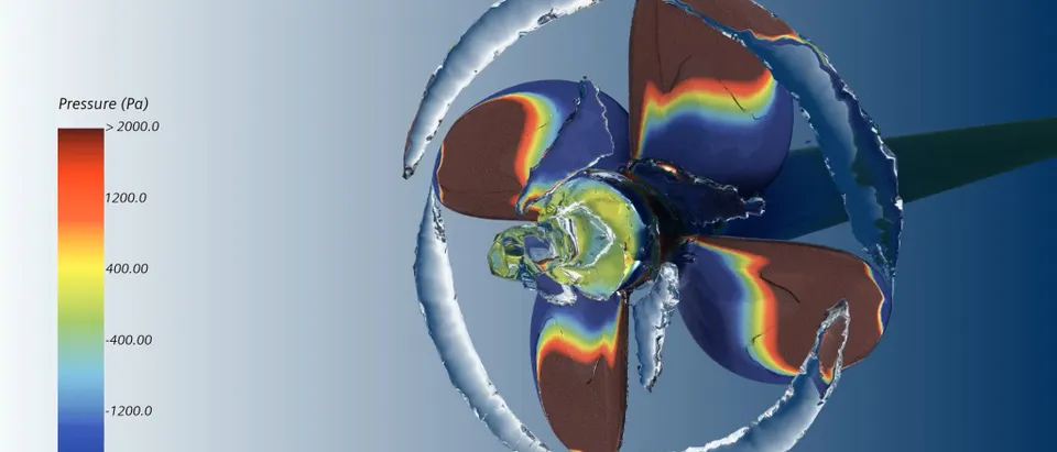
Propeller cavitation is the formation of vapour where the pressure on or around a blade falls below the vapour pressure of water. A little of it is often unavoidable. Too much of the wrong kind costs thrust, erodes blades, sends pressure pulses into the hull and makes a ship the loudest thing in its part of the ocean.
Noise has become a design requirement in its own right. The IMO first issued guidelines on underwater radiated noise from commercial shipping in 2014 and revised them in 2023 and again in 2024 (MEPC.1/Circ.906/Rev.1). They remain voluntary, but they ask owners to manage noise across design and operation, and the GloNoise partnership supports their implementation. Classification societies offer quiet-ship notations, and naval and research vessels have long had strict signatures to meet. The IMO's work on ship noise gives the background.
The forms of propeller cavitation
Cavitation is governed by the cavitation number, σ = (p0 − pv) / ½ρV2: the margin between the local static pressure and the vapour pressure, scaled by the dynamic pressure. Wherever the pressure coefficient on the blade drops below −σ, vapour can form. Because the propeller turns through the uneven wake behind the hull, the blade loading, and so the cavitation, changes every revolution.
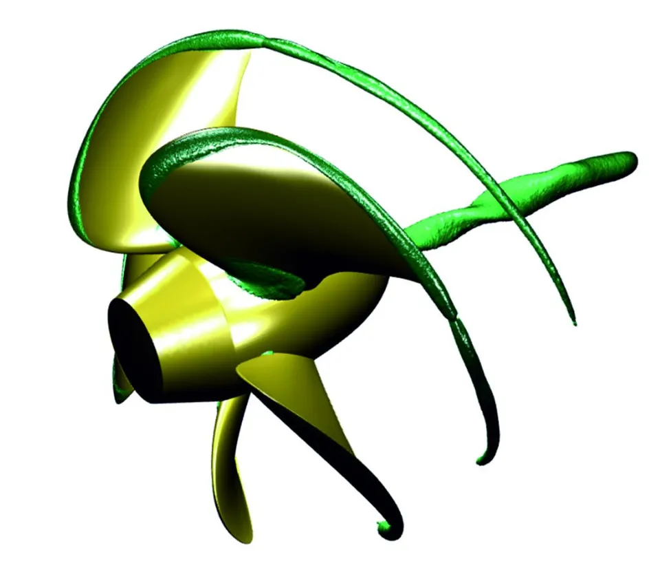
- Sheet cavitation. A vapour sheet near the leading edge on the suction side. Its growth and collapse each revolution drive pressure pulses on the hull.
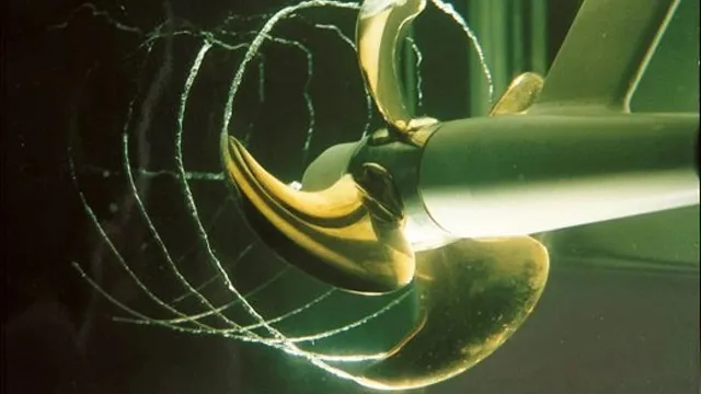
- Tip-vortex cavitation. Vapour in the low-pressure core of the tip vortex: often the first type to appear, and a strong noise source.
- Cloud cavitation. Shedding and collapsing clouds of bubbles: the classic cause of erosion as well as broadband noise.
- Hub vortex. The vortex behind the boss. Boss-cap fins and hub shape can weaken it.
- Blade-rate tones. Narrow peaks at the blade-passing frequency and its harmonics, from blade loading that varies in the non-uniform wake.
- Broadband cavitation noise. Raised levels across a wide band once cavitation sets in: the main concern of underwater-noise guidelines.
- Sheet cavitation forms near the leading edge on the suction side. Its growth and collapse each revolution drive pressure pulses on the hull above the propeller.
- Tip-vortex cavitation fills the low-pressure core of the vortex shed from each blade tip. It is often the first type to appear and a strong source of noise.
- Cloud and bubble cavitation appear when sheets break up and collapse. They are the classic cause of erosion and of broadband noise.
- Hub-vortex cavitation forms behind the boss; boss-cap fins and hub shaping can weaken it.
Why propeller cavitation matters beyond efficiency
| Effect | Mechanism | Where it bites |
|---|---|---|
| Thrust and efficiency loss | Vapour changes the blade's effective shape | Speed, fuel and bollard pull |
| Erosion | Collapsing clouds hammer the blade surface | Blade repair and replacement |
| Hull pressure pulses | Sheet volume changing each revolution | Vibration, comfort and fatigue in the stern |
| Underwater radiated noise | Tip vortex, sheet and cloud collapse | Marine life, sonar performance, noise notations |
| Onboard noise | Pressure pulses and structure-borne transmission | Crew and passenger accommodation |
These effects pull in different directions. A propeller loaded harder at the tip is often more efficient and also cavitates earlier; unloading the tip quietens it but can cost efficiency. Designing a propeller is therefore a multi-objective problem, and the trade-off has to be seen, not guessed.
Predicting cavitation and noise with simulation
A practical prediction chain moves from fast to detailed tools, using each where it is reliable.
- Wake. The propeller's inflow comes from a resistance or self-propulsion CFD of the hull, at full scale where possible, because the wake decides the unsteady loading.
- Fast screening. Lifting-surface or boundary-element methods estimate sheet cavitation and pressure pulses across many blade designs quickly.
- Detailed CFD. RANS or scale-resolving simulations (DES or LES) with a cavitation model, such as a Schnerr–Sauer mass-transfer model, resolve sheet, tip-vortex and cloud dynamics on the shortlisted designs. Resolving the tip vortex needs a fine, well-placed mesh along its path.
- Acoustics. An acoustic analogy such as Ffowcs Williams–Hawkings propagates the pressure sources to the far field to estimate radiated noise; hull pressure pulses feed a structural model for vibration.
- Validation. Cavitation-tunnel observations, measured pressure pulses and, where available, noise trials anchor the chain.
Honest about the hard part
Where AI helps design a quiet propeller
- Multi-objective optimisation. Surrogates trained on BEM and CFD runs let an optimiser trade efficiency, cavitation margin, pressure pulses and noise across thousands of blade geometries, calling CFD only to confirm. See generative design and optimisation.
- Wake-to-noise models. Learned mappings from wake field and operating point to cavitation extent give early warnings while the hull is still changing.
- Operational noise management. The same models estimate noise at different speeds and loading, the information a noise management plan needs.
- Physics-informed learning. Where data is scarce, physics-informed machine learning constrains models with the governing equations.
From one study to a capability you keep
A single simulation campaign answers the question it was asked. The larger return comes when the setup becomes a workflow your own team runs. The next variant, loading condition or operating question then costs hours instead of weeks, and every answer is checked the same way. That is how we build propulsion, cavitation and noise work.
- Physics model. CFD and FEA set up once, as templates: geometry clean-up, mesh, solver settings and post-processing that every later run reuses.
- Validation. Mesh and time-step studies, and comparison with tests or full-scale data, so the model's uncertainty is known before it is trusted.
- Automated runs. Scripted runs over the parameters and operating conditions that matter, on your hardware or in the cloud.
- AI surrogate. A machine-learning model trained on those runs answers in seconds and says how sure it is; low-confidence questions go back to the solver.
- Decision tool. Optimisation, trade-off charts or operating guidance, in a form your engineers and operators use every day.
- Field data. Test, trial and monitoring data flow back to recalibrate the model, so it improves with every project instead of being rebuilt.
- Templates for geometry, mesh, solver settings and post-processing, documented so results stay consistent from one variant to the next.
- A validation record that ties the simulations to your tests, trials or field data, with the uncertainty stated.
- Automated runs over the parameters and operating conditions that matter, on your hardware or in the cloud.
- A trained surrogate and a simple decision tool, with the limits of its validity written down.
- Training and handover, so your engineers can extend the workflow themselves. See our training and software development services.
Questions about propeller cavitation
Can CFD predict cavitation inception?
Is underwater radiated noise regulated?
Does reducing noise always cost efficiency?
What inputs do you need?
Cavitation and noise connect our propulsion and cavitation work with shipbuilding noise engineering and multiphase flow. For the hull side of the problem, see our article on ship resistance and propulsion CFD. If a propeller has to be efficient and quiet, talk to us.