Airbag deployment simulation that stays true in out-of-position cases
A folded cushion opens in milliseconds, and an occupant close to the module meets it mid-unfolding. Gas models, fabric and fold inputs, tank-test calibration and validation decide whether the simulation tunes the airbag or only decorates a report.
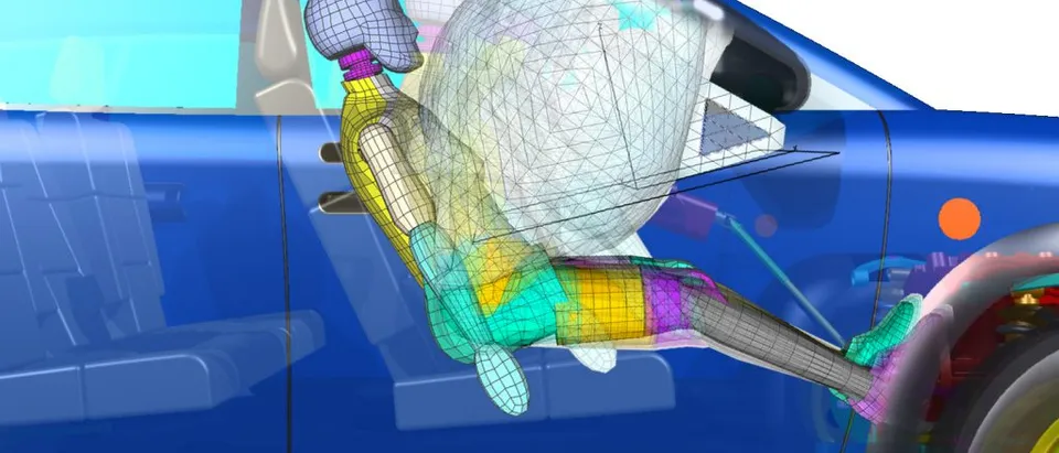
Airbag deployment simulation predicts how a folded cushion opens, fills and loads an occupant, so the fold, vents, tethers and inflator can be tuned before the next sled or vehicle test. We build it as a workflow around Ansys LS-DYNA, ESI Pam-Crash or Simulia Abaqus: a calibrated inflator and fabric record, a gas model chosen for each load case, and a validation record your team keeps.
The first deployment film of the new passenger airbag shows the cushion reaching the dummy's head while it is still unfolding. A different fold, a smaller vent or a softer inflator stage each needs a new batch of cushions and a new sled slot, and a fix for the early contact can cost the ride-down. Which change helps, and what it costs the other load cases, is the decision the design review is waiting for.
What does airbag deployment simulation have to get right?
An airbag is a thin, porous, orthotropic fabric structure, folded in layers, driven by a hot gas jet within milliseconds. It contacts itself, the module, the windscreen and the occupant. Explicit finite elements in LS-DYNA, Pam-Crash and Abaqus handle the fabric and contact. The hard part is the gas.
The oldest gas model treats the bag as one control volume. Per Hirth, Haufe and Olovsson, “Airbag Simulation with LS-DYNA: Past, Present, Future” (6th LS-DYNA Anwenderforum, 2007), the uniform-pressure technique goes back to Wang and Nefske in the late 1980s: the bag volume comes from the geometry at every time step, the gas is ideal, and one pressure loads every face. For an ideal gas the pressure follows p = (γ − 1) ρ e, and the energy of the gas in the bag changes as dE/dt = cp ṁin Tin − cp ṁout T − p dV/dt. The inflow and its temperature come from a tank test. The outflow splits into vent holes and fabric porosity. Through an orifice the flow chokes at high pressure and then no longer depends on the downstream pressure.
- Folded cushion. The bag leaves the factory as layers of fabric folded in a set pattern. The fold pattern is part of the design: it decides which layers open first and how the bag meets an occupant. A simulation starts from this folded geometry, not from a tidy inflated shape.
- Unfolding under the gas jet. Gas leaves the inflator as a high-momentum jet, and the folds open one after another. Pressure in the bag is far from uniform, and the front of the cushion moves fast. An occupant seated close to the module is touched at this stage.
- Fully inflated. The cushion reaches its full volume and the gas spreads out. Vents and fabric porosity begin to bleed gas, and the pressure in the bag is close to one value.
- Ride-down. The occupant loads the bag and gas leaves through the vents. The vent area and fabric porosity set how much energy the bag takes out of the occupant, so they belong in the tuning, next to the inflator.
- Out-of-position window. An occupant close to the module, as in the out-of-position cases a frontal-protection standard specifies, meets the bag in the unfolding stage. The load on that occupant is set by the local gas flow and the moving fabric front.
- Resolved flow against one pressure. A model with a single pressure in the bag (solid versus dashed curve) tracks the later stage well and has no local flow in the early one. A model that resolves the gas shows the early peak that the close occupant meets. The sketch is qualitative.
Why do out-of-position cases change the model?
Because the standards test them. 49 CFR 571.208 (FMVSS No. 208) sets low risk deployment tests for the driver and passenger air bag. For the driver, S25.3 requires the injury criteria to be met when the air bag is “statically deployed” in both procedures of S26, with the 5th percentile adult female dummy placed in “Driver position 1 (chin on module)” and “Driver position 2 (chin on rim)”. S26.4 adds that a multistage inflator must comply “at any stage or combination of stages or time delay between successive stages” that could occur in a rigid barrier crash test at or below 26 km/h. For the passenger side, S20.4 uses the 12-month-old CRABI dummy in a rear-facing child restraint, and S19.4.2 limits HIC15 to 390 there. The driver criteria of S15.3, which S25.3 invokes, limit HIC15 to 700.
HIC15 is the maximum over any window of up to 15 ms of (t2 − t1) [ (1/(t2 − t1)) ∫ a dt ]2.5, with a the resultant head acceleration in g.
In these cases the dummy touches the cushion while it is still unfolding. Hirth et al. note that the uniform-pressure model neglects local fluid effects, which matters little when the occupant meets an almost fully deployed bag and a great deal for out-of-position loading, where a physically correct model of the flow is needed. Chawla, Mukherjee, Jangra and Nakatani, “Issues in ALE Simulation of Airbags” put it on one folded passenger bag against high-speed film: the control-volume and ALE predictions differ most in the earliest part of the deployment and become similar later, and the bag height lags the film more with the control volume than with ALE.
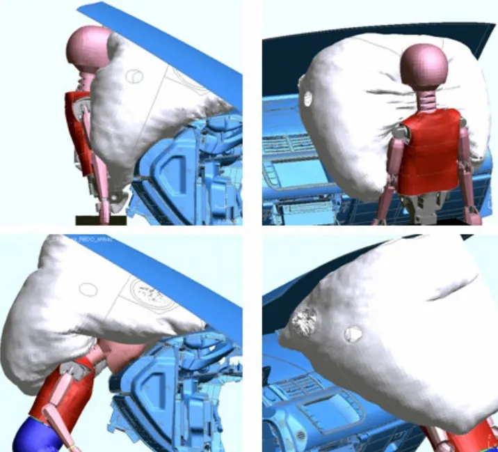
Control volume, ALE or particles: which gas model fits which airbag case?
The methods differ in how much early gas flow they resolve, and at what cost.
- Control volume. One pressure, no gas mesh, negligible cost next to the structure. It suits later stages, ride-down and wide sweeps. Jetting options add momentum along the inflator jet but, per Chawla et al., not the redirection of gas around obstacles.
- ALE. The gas is an Eulerian mesh coupled to the Lagrangian fabric by a penalty contact. It resolves jets and local pressure. Per Hirth et al., the vent outflow depends strongly on the Eulerian mesh size, and when two fabric patches lie parallel inside one gas cell, as in tubes of a window bag pressing on each other, the coupling can give unphysical shapes and penetrations.
- Particles. The gas is a cloud of particles, each representing many molecules, with pressure set by their kinetic energy. Gas reaches into tight folds and through narrow gaps without a mesh, but the particle count has to suit the volume. On a flat bag the same source reports the particle run clearly faster than ALE, and by far less so on a multi-chamber window bag.
The same source shows the methods opening the same folded tube very differently and leaves the verdict to experiments. A deployment film and an impactor test decide it, and the choice is recorded per load case.
- Uniform pressure (control volume). The bag is one thermodynamic volume: mass in from the inflator, mass out through vents and fabric, one pressure applied to every face. There is no gas mesh, so it is fast and it carries no local flow. Jetting options add momentum along the jet.
- ALE: gas mesh coupled to fabric. The gas lives on a fixed or moving Eulerian grid, the fabric is a Lagrangian shell mesh, and a penalty coupling transfers force between them. It resolves jets and local pressure. Results depend on the gas mesh size, and layers of fabric inside one gas cell need care.
- Particles (corpuscular method). The gas is a cloud of particles, each standing for many molecules. Pressure comes from the particles hitting the fabric, so gas passes through tight folds and narrow gaps without a mesh. The particle count has to be high enough for the volume to fill.
- Inflator tank test. The inflator fires into a closed tank and the pressure history is recorded. The mass-flow and temperature curves that drive every method are derived from it, so an error here travels into all three.
- Fabric, vents and porosity. Biaxial and picture-frame tests give the fabric law. Vents are modelled as real holes, and porosity as a leakage curve against pressure difference. Uniaxial tension alone does not describe the bag.
- Folded bag mesh. The initial geometry, with layers and tucks in their folded positions and no penetrations between them. Getting it right is a modelling task of its own, and it is done once per bag design and then scripted.
- Component-test comparison. Free deployment film and an impactor test give curves to compare with the simulation. A mismatch goes back to the inputs above: recalibrate, rerun and keep the record.
| Question | Gas model | What feeds it | What to watch |
|---|---|---|---|
| Fold, vent or tether sweep, occupant in position | Control volume | Tank-test mass flow, temperature, porosity | No local flow: not for early contact |
| Out-of-position driver or child dummy, early contact | ALE or particles | Same inputs, folded mesh without penetrations | Gas mesh size or particle count |
| Multistage inflator timing | Control volume to screen, ALE or particles to confirm | Stage curves and delay combinations | Every combination the standard names |
| Side curtain or multi-chamber bag | Particles, or ALE with a fine gas mesh | Chamber, seam and tether geometry | Fabric layers inside one gas cell |
| Many variants and occupant positions | Surrogate on top of the chosen model | A planned run set | Stated range, gate to the full model |
A model matched to the tank and the film has proved the fit, not the design
Where do the folding, fabric and inflator inputs come from?
Fabric. Hirth et al. point to biaxial and picture-frame tests as the basis of the fabric law. Uniaxial tension data alone does not reproduce the biaxial response: the first hump in the biaxial curve comes from warp and fill threads interacting.
Folding. The folded mesh is a modelling task in its own right. Chawla et al. report that folding by rotating rigid planes worked for up to two folds. For more, they mapped nodes at every fold location through all fabric layers, rotated the node groups by 180 and 90 degrees, and removed layer-to-layer penetrations by moving nodes. We script this once per bag design, so a new fold is a parameter, not a new meshing job.
Inflator and vents. The tank test gives the pressure history from which the mass flow and temperature curves are derived. Vents are real holes in the mesh. Porosity is a measured curve of gas velocity through the fabric against pressure difference. Each is a calibration target, and each goes into the record with its conditions.
Where does machine learning help airbag design, and where does it not?
- Calibration. Fitting inflator and porosity parameters to the tank and deployment data is an inverse problem. A Bayesian or optimisation loop returns parameters with their uncertainty and shows what the data does not pin down.
- Surrogates over the design space. A model trained on a planned run set over fold, vent area, tether length, inflator stage and occupant position returns head, neck and chest metrics for new candidates without a new run. See surrogate models for CFD and FEA.
- Worst-case search. Adaptive sampling places the next resolved-gas run where the occupant position or timing is most severe.
- Run gates. Energy balance, initial penetration and particle-count checks flag bad runs before anyone reads their curves.
It does not replace the gas-fabric physics. A trained model cannot know the early contact of a fold or inflator it was never shown, so outside its range the request goes to the full model. Nor does it turn a metric into an injury outcome. The validation record is what lets you sign off a result. See AI surrogate models you can sign off and our crash model validation article.
From one tuned airbag to a deployment capability you keep
The return comes when your own team can run a new fold, vent or inflator variant and read a validated answer before the sled slot, without rebuilding the model.
- Physics model. CFD and FEA set up once, as templates: geometry clean-up, mesh, solver settings and post-processing that every later run reuses.
- Validation. Mesh and time-step studies, and comparison with tests or full-scale data, so the model's uncertainty is known before it is trusted.
- Automated runs. Scripted runs over the parameters and operating conditions that matter, on your hardware or in the cloud.
- AI surrogate. A machine-learning model trained on those runs answers in seconds and says how sure it is; low-confidence questions go back to the solver.
- Decision tool. Optimisation, trade-off charts or operating guidance, in a form your engineers and operators use every day.
- Field data. Test, trial and monitoring data flow back to recalibrate the model, so it improves with every project instead of being rebuilt.
- A scripted folded-bag model in your existing crash solver: fold pattern, fabric law, vents, tethers and module, checked for initial penetrations.
- An inflator and fabric record: tank-test curves, fitted mass-flow and temperature inputs, the porosity curve and the conditions they cover.
- A gas-method rule per load case: early-contact runs resolve the gas, screening runs use the cheaper model.
- Automated run sets over fold, vent, inflator stage and occupant position, with energy-balance and penetration gates.
- A validation record tying film, impactor and tank tests to the model, with fit data kept apart from check data.
- A surrogate with a stated range over the variables you change, returning out-of-range requests to the full model.
- Handover and training, so your engineers extend it themselves. See our training and software development services.
Questions engineers ask about airbag deployment simulation
What is airbag deployment simulation?
Which method should I use for out-of-position cases?
What test data do I need to calibrate the model?
Can simulation replace the physical airbag tests?
What do you need from us to start?
If an early-contact film or an out-of-position case is on your desk, send us the inflator tank-test record, the cushion mesh or fold drawing, the fabric and vent data you hold, and the deployment or impactor test you want the model to match, with the load cases and stage timings that concern you. We will reply with the gas model we would use for each case, what we would calibrate first, and what the validation record would contain. Start with a conversation, or read about our airbag effectiveness work and the crash test simulation section.