Seat whiplash simulation for head restraint and seat-back design
A seat's rear-impact result turns on backset, recliner yield and the moment the head meets the restraint, and one sled run cannot separate them. A simulation workflow built on your explicit solver can, before the prototype and the sled slot are committed.
Seat whiplash simulation predicts how a seat, its head restraint and a rear-impact sled pulse load the neck of a BioRID-type dummy model, so backset, recliner yield and seat-back stiffness can be tuned before a sled slot is spent. We build that workflow around your existing explicit solver, with the dummy model, load cases and correlation record that the Euro NCAP and IIHS rear-impact procedures read.
The seat is frozen except for three things: where the head restraint sits, how the recliner yields and what the seat-back frame may do. A prototype build, a sled booking and a tooling release stand behind them. A yielding recliner lowers torso acceleration but can delay head contact; a nearer restraint brings contact forward. One sled run cannot say which change moved which metric.
What happens to the neck in a rear impact?
Struck from behind, the vehicle and seat accelerate forward. The seat back loads the torso first, and the head, carrying no load, waits until the gap to the restraint, the backset, has closed. For a free head and constant seat acceleration a, a gap g closes at t = √(2g/a), so backset sets when the head is picked up. IIHS's Version V protocol puts it as support: the farther the restraint is from the head, the more head and torso move separately, creating potentially injurious forces on the neck.
While the head lags, the neck changes shape. In cadaver spine sled tests it formed an S-shaped curvature, lower levels in hyperextension while upper levels were in flexion, then a C-shaped curvature of the whole neck (Grauer and colleagues, 1997, abstract). A BioRID-type dummy reads that loading as upper-neck shear and tension, bending moments, and the acceleration difference between the T1 vertebra and the head.
- Seat back loads the torso. The seat back accelerates with the sled and pushes the torso forward. The T1 accelerometer on the upper thoracic spine of the dummy reads it, and its peak is a seat-design number in the IIHS and Euro NCAP procedures.
- Backset: the head waits. The head carries no load until it meets the restraint, so the gap decides when it is picked up. For a free head and a constant seat acceleration a, a gap g closes at t = √(2g/a).
- The neck takes an S shape. While the head lags, the lower neck is in extension as the upper neck is still in flexion: the S shape seen in cadaver sled tests (Grauer et al., 1997). Neck shear, tension and NIC read this loading in the dummy.
- Recliner and seat back yield. A recliner that yields at a limit moment lets the back rotate and absorbs energy, which lowers the torso acceleration. The dashed outline is where the back started; Euro NCAP reads the change of angle as seat-back deflection.
- The head meets the restraint. A contact switch marks the contact, which counts once it lasts more than 40 ms. The head then rebounds, and Euro NCAP reads its rebound velocity relative to the sled from film.
- The window the metrics read. Peak neck forces and T1 acceleration are taken from the start of the pulse to the end of head contact, as Euro NCAP's CP 005 states. Everything after the head leaves the restraint is outside the score.
Euro NCAP's technical bulletin CP 005 defines the T1-to-head difference as NIC = 0.2arel + vrel², with arel the T1 minus head acceleration along x and vrel its integral. Neck forces, T1 acceleration and Nkm are taken from the start of the pulse to the end of head contact, which counts once it lasts more than 40 ms; what the head does after leaving the restraint is outside the score.
The seat back is not a rigid wall. A recliner or hinge that yields at a limit moment M absorbs energy W = ∫M dθ as the back rotates, lowering the torso acceleration the restraint must follow. IIHS sets its T1 limit from Volvo WHIPS seats, which have energy-absorbing, force-limiting seatback hinges, and notes such designs may bring later head contact. Euro NCAP reads the other side of the trade: seat-back dynamic deflection, the change in angle between the seat-back targets and the sled base.
What do Euro NCAP, IIHS and FMVSS 202a actually measure?
Euro NCAP's Rear Impact Protocol, version 1.2 of July 2026, seats a BioRID UN dummy on a reverse-acceleration sled, the only type it accepts for the official seat assessment, and runs a medium pulse at a velocity change of 15.65 ± 0.80 km/h and a high pulse at 24.45 ± 1.2 km/h. Of 5 rear-impact points, front occupants carry 4, 3 of them dynamic. NIC and upper-neck shear and tension carry the points; Nkm, head rebound velocity, T1 acceleration, head contact time and seat-back deflection set capping limits.
IIHS's dynamic protocol, Version V of December 2019, uses a BioRID IIg on a 16 km/h pulse, roughly triangular with a 10 g peak and a 91 ms duration. Its two seat design parameters are head contact under 70 ms and a maximum T1 acceleration below 9.5 g. Neck shear and tension are graded low, moderate or high, and a good rating needs one design parameter and low neck forces.
IIHS's draft Whiplash Prevention Evaluation protocol, Version II of June 2026, calls itself the first IIHS ratings programme to include computer simulations. An automaker submits physical or simulation results for 16 and 24 km/h pulses, IIHS audits one at random with its own sled test, and both are accepted if they align.
FMVSS 202a (49 CFR 571.202a) is a different kind of test. A head restraint conforms to either a static route, dimensional and structural, or a dynamic route with a Hybrid III 50th percentile male, not a BioRID.
| Procedure | Dummy and load | What it reads | What your model carries |
|---|---|---|---|
| FMVSS 202a static route (S4.2) | No dummy: H-point manikin, head forms, moment loads | Height at least 800 mm, backset at most 55 mm, head form at most 80 g for 3 ms, 373 N·m moment test | Seat-back and restraint structure, foam, static and impact load cases |
| FMVSS 202a dynamic route (S4.3) | Hybrid III 50th male, 17.3 km/h platform | Head-to-torso rotation 12°, HIC15 500 | Seat, Hybrid III with rotation sensors, platform pulse |
| Euro NCAP rear impact v1.2 | BioRID UN, 15.65 and 24.45 km/h pulses | NIC, neck shear and tension scored; Nkm, T1, contact time, rebound, deflection cap | BioRID model, recliner yield, seat-back deflection, restraint contact |
| IIHS dynamic, Version V | BioRID IIg, 16 km/h pulse, 10 g peak | Contact under 70 ms, T1 under 9.5 g, neck forces low to high | Contact and T1 channels in the model |
| IIHS draft, Version II | BioRID-II, 16 and 24 km/h, one audited | Time histories and peak metrics match an IIHS sled test | Qualified dummy, explicit solver, energy checks |
How are whiplash seats developed today, and where does that break?
Mostly on the sled, and that is where the method runs out of information.
- One run, one sample. A run returns a handful of peaks at one pulse, one seating and one seat unit, and cannot say whether backset, recliner or foam moved them. The IIHS draft itself recommends simulations at pulses spanning its own sled's range.
- One occupant. A BioRID represents a 50th percentile male. Carlsson and colleagues (2021) found it an insufficient representation of the average female for the dynamic seat response, with no simple way to scale its data.
- Dummy artefacts. The Euro NCAP protocol carries a −1 modifier for exploiting a dummy artefact, found on inspection. A seat tuned only to the dummy can pass for the wrong reason.
- Late models. A seat model built after the test to explain it arrives after the tooling release it could have guided.
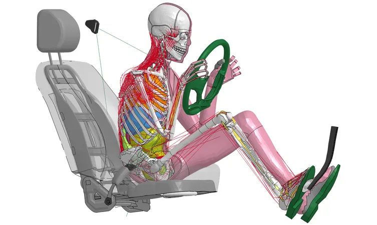
How is seat whiplash simulation done properly?
The model has three parts, built to the protocol's tolerances: the seat (frame, recliner and hinge, seat-back suspension, foam, trim and head restraint posts, calibrated on component tests such as the 373 N·m moment test of FMVSS 202a), the dummy, and the sled pulse as prescribed rigid-body motion. The IIHS draft names two pre-approved dummy models, DYNAmore's LS-DYNA BioRID-II and the PAM-SAFE BioRID model, and asks approval for others. We build seat models in Ansys LS-DYNA, Simulia Abaqus, ESI Pam-Crash or Altair RADIOSS.
Verification follows the draft's own checks: hourglass energy below 5% of internal energy, added mass below 5% of physical mass, 15 ms of equilibrium before the pulse, no body-force pulses. Validation compares head, T1, L1 and pelvis acceleration histories with a physical run; the draft scores them with ISO 18571 at 0.7 or more, and wants a normalised peak-metric error below 1. Uncertainty covers pulse variation inside the corridor, seating tolerances, recliner friction and foam scatter, swept into a range.
A simulated result is not a rating
- Recliner yield limit. A yielding recliner or hinge holds until a limit moment, then rotates. The energy it absorbs is the area under the moment-rotation curve, W = ∫M dθ. The limit moment is one tuning variable, with backset, foam and head restraint stiffness.
- Torso acceleration falls. IIHS's Version V sets its T1 limit from seats with energy-absorbing, force-limiting hinges. The curves are qualitative: their shape comes from your seat model, not from this drawing.
- Head contact comes later. IIHS notes that energy-absorbing seat designs may result in later head contact. Both programmes read contact time, so a gain in torso acceleration can cost timing.
- Seat-back deflection grows. The more the back yields, the more its angle changes during the test, which Euro NCAP reads as deflection. The limit line stands for the limit your programme sets.
- The tuning window. Where torso loading, contact time and deflection are acceptable together. It is narrow and moves with backset, foam, pulse and dummy model, so a sweep finds it and a single sled run does not.
- Runs, surrogate and range. Each full-model run, a dot, gives all three results at once, and a surrogate through them is cheap to sweep. The bracket is the range of the runs: a request outside it goes back to the full model.
Where does AI help seat whiplash design, and where does it not?
- Tuning surrogate. Runs over backset, recliner limit moment, hinge stroke, foam and head restraint stiffness train a surrogate that returns T1 acceleration, contact time, deflection, neck loads and NIC anywhere inside its range; the full model keeps the designs that decide. See surrogate models for CFD and FEA.
- Calibration. Recliner and foam parameters are fitted to your component tests by an inverse method that returns a range, which enters the uncertainty record.
- Artefact screening. A script flags runs whose energy ratios or time-history scores drift from the validation record, and designs whose neck loads jump when the dummy model is perturbed.
It does not replace occupant data. A surrogate cannot predict outside its range, inherits every error of the seat and dummy models, and finds artefacts if an optimiser is allowed to. It is only as representative as the occupant models behind it. See AI surrogate models you can sign off and our crash test dummy article.
From one sled correlation to a whiplash capability you keep
The return comes when your engineers can put the next recliner, backset or foam change through the same chain without rebuilding anything.
- Physics model. CFD and FEA set up once, as templates: geometry clean-up, mesh, solver settings and post-processing that every later run reuses.
- Validation. Mesh and time-step studies, and comparison with tests or full-scale data, so the model's uncertainty is known before it is trusted.
- Automated runs. Scripted runs over the parameters and operating conditions that matter, on your hardware or in the cloud.
- AI surrogate. A machine-learning model trained on those runs answers in seconds and says how sure it is; low-confidence questions go back to the solver.
- Decision tool. Optimisation, trade-off charts or operating guidance, in a form your engineers and operators use every day.
- Field data. Test, trial and monitoring data flow back to recalibrate the model, so it improves with every project instead of being rebuilt.
- A seat template in your explicit solver: recliner and hinge, seat-back suspension, foam, trim and head restraint, parametrised for backset, yield limit and stiffness.
- A positioning macro that seats the dummy model to the protocol's tolerances and checks them before every run.
- A load-case library of the pulses you are rated under, with the variants inside each corridor, and the static head restraint loads.
- Scripted post-processing that reads NIC, Nkm, T1, contact time, rebound and deflection over the window the bulletin defines.
- A validation record against your sled runs, tolerances set before the run, and a surrogate with a stated range behind a gate that sends anything outside it to the full model.
- Handover and training, so your team runs and extends it. See our training and software development services, and the seat design hub.
Questions engineers ask about seat whiplash and head restraints
What is head restraint backset?
Which dummy do whiplash tests use?
Can simulation replace the sled test?
Do whiplash dummies represent women?
If a head restraint or recliner release is waiting on a sled slot, send us the seat-back and head restraint model or drawing with the recliner and hinge definition, the dummy model and version you use, the protocol version you are rated under, and one sled run with head, T1 and neck channels and film. We reply with how we would build the model, the correlation we would show against your run, and the parameters we would put in the surrogate. Start with a conversation, or read the NCAP whiplash and FMVSS 202a capability pages.