Aircraft seat crash simulation that prepares your 16g and 14g dynamic tests
A seat that fails its first sled test costs a build, a test slot and a date. Simulating the forward and downward conditions of 25.562 shows the track load, the head path and the critical configuration before the seat goes on the sled.
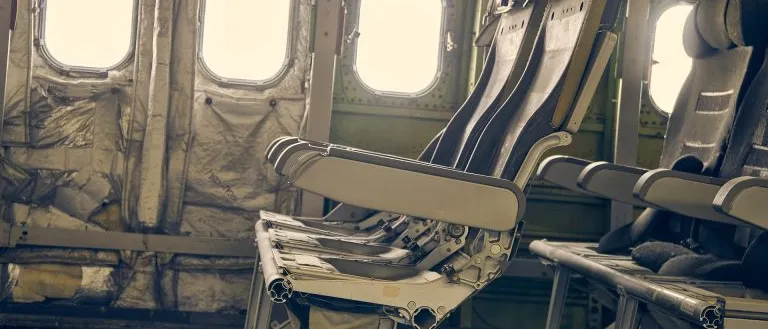
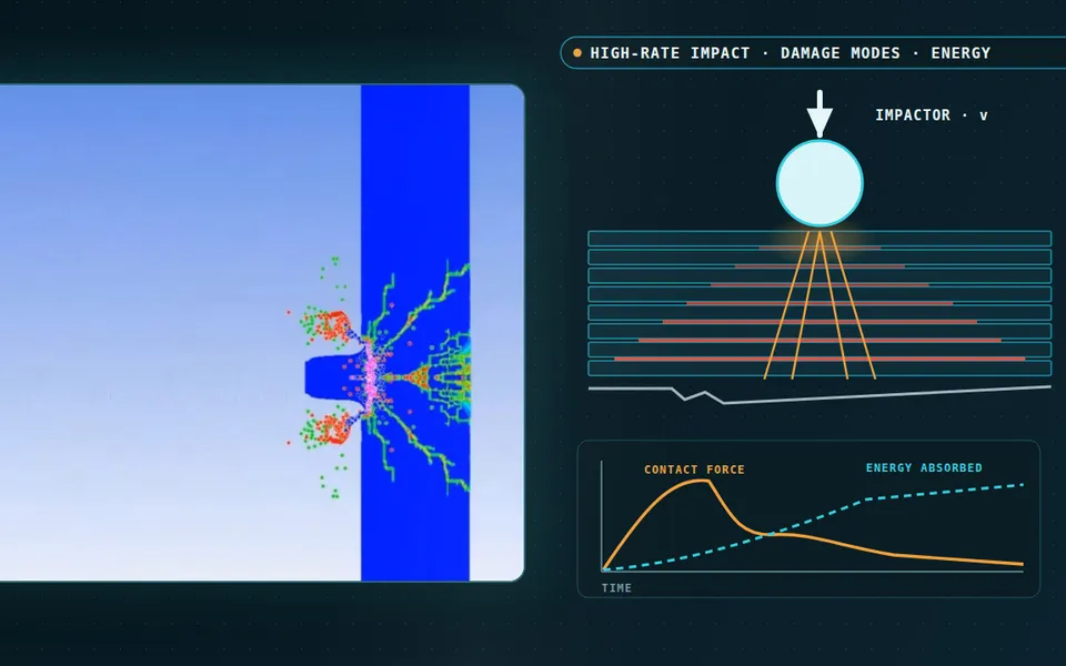
Aircraft seat crash simulation reproduces the two dynamic conditions of 14 CFR 25.562 and CS 25.562, a downward pulse of at least 14 g and a forward pulse of at least 16 g, in a validated finite-element model of seat, floor interface and dummy. It shows which configuration to put on the sled first, where the seat loads the track and how far the head travels, so the physical test confirms a design instead of discovering its problems. We build the workflow around your existing explicit solver, and acceptance of any analysis stays with your certifying authority.
The seat is built and the sled slot is booked. In the forward test a rear leg pulls out of its track, or the dummy's head reaches the seat ahead hard enough to take HIC over its limit. The seat goes back to design, the next build and slot queue behind it, and your programme date moves.
What do the 25.562 and CS 25.562 dynamic tests require?
Both texts require each seat type approved for occupancy to pass dynamic tests, or to be shown by rational analysis based on tests of a similar seat, with a 170 lb (77 kg) dummy sitting upright. In 25.562(b) the downward condition is a velocity change of not less than 35 ft/s with the airplane's axis canted down 30 degrees and a peak floor deceleration of at least 14 g within 0.08 s. The forward condition is not less than 44 ft/s with the airplane yawed 10 degrees and a peak of at least 16 g within 0.09 s, on rails misaligned by at least 10 degrees vertically with one rolled 10 degrees. CS 25.562 gives the same conditions in metric units.
Paragraph (c) sets the criteria: lumbar compression of no more than 1,500 lb, HIC of no more than 1,000 where the head can strike the seat or other structure, axial femur load of no more than 2,250 lb, a lap belt that stays on the pelvis, and a seat that stays attached at every point of attachment although the structure may have yielded, without yielding so far that it impedes evacuation.
AC 25.562-1B explains how the tests are run. EASA's AMC 25.562 accepts it, as amended by Change 1, with AC 20-146A, as a means of compliance with CS 25.562, and AC 20-146A defines when a validated model may support dynamic testing or stand in for it on a modified seat.
- Pre-deformed floor. Before the pulse, the rails under the seat are pitched under one pair of legs and rolled under the other, so the seat is twisted and pre-stressed when the load arrives. The test shows that it stays attached and works even when the floor has deformed. A model that starts from a flat floor answers an easier question.
- Lap belt. The belt holds the pelvis and passes the occupant's inertia into the frame at its anchors. Belt load history and anchor position decide how far the pelvis moves and how much the torso folds forward, so both are compared with the test instead of assumed.
- Load path to the rear stud. From the belt anchors the force runs down the legs into the rails. The forward inertia force acts above the floor, so the seat tries to rotate forward and the rear leg is pulled up out of its track. That floor interface is where the aircraft maker and the track set load limits.
- Controlled deformation. The structure is meant to give in a controlled way: a crush or bending element absorbs energy so that less load reaches the track. Too stiff, and the load goes into the stud. Too soft, and the seat moves too far. The model has to reproduce where the deformation starts and how it grows.
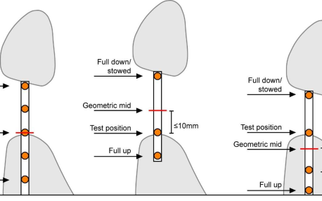
- Head path and strike zone. The head swings forward on the arc the lap belt allows. Whether it reaches the seat or monument ahead, where, and at what speed, depends on seat pitch, belt geometry and seat deformation. If contact can happen, the head injury criterion is evaluated there. If it cannot, the result is a clearance.
- Sled pulse. The sled decelerates along a prescribed pulse with the seat yawed, and every mass on it is loaded through its own inertia. The pulse in the model has to match the pulse the test house recorded, rise and peak included, because stud load and head path both follow it.
Why is aircraft seat crash simulation hard?
The seat is asked for two opposite things: stiff enough to keep the occupant's space, soft enough to absorb energy. A 2006 LS-DYNA study from Hamburg University of Applied Sciences calls the 16 g forward case the most critical for that reason: a structure that is too stiff puts high tensile loads into the track at the rear floor attachments. In the simplest picture the seat absorbs the kinetic energy of the mass it carries, ½mΔv2, and a load limit F over a stroke s absorbs F·s. Halving the track load doubles the stroke, and the stroke is bounded by the space available.
- Too soft: lost space. The softer the structure, the further it deforms under the forward load. Permanent deformation eats the space the occupant needs, and a seat that yields too far can impede evacuation or lose its attachment. The curve falls as stiffness rises.
- Too stiff: track load. The stiffer the structure, the less energy the seat absorbs and the more load reaches the rear floor attachment. The curve rises, steeply at the stiff end. This is the trade that makes the forward condition the critical one for seat structure.
- Allowables. Two limits bound the design: how far the seat may deform permanently, and how much load it may put into the track, set by the aircraft maker and the track. Real tests sit near these lines, which is why model error near them matters more than error far away.
- The window. Only the stiffness range where both limits hold is usable. Its edges are where the curves meet the limits, and model uncertainty turns each edge into a band. A narrow window leaves little room for variation in material, build or installation.
- Occupant mass and size. The same seat meets lighter and heavier occupants, and both curves move. A seat tuned for one extreme can be too stiff for a light occupant and too flexible for a heavy one, so the window is checked across the range the programme covers, not at a single point.
- Lighter section, same window. Taking material out to save weight usually moves the design point to the soft side, and a different laminate or machined part moves the curves themselves. A simulation sweeps this axis, so section, material and absorber are chosen against both curves together before a seat is built.
The starting state is not clean. In the forward test the rails are pre-deformed, so the seat is twisted before the pulse. AC 25.562-1B describes a fixture with a pitch beam and a roll beam, each moving 10 degrees either way, to show that the seat stays attached while the floor is deformed. The Hamburg paper found that pre-deformation alone can load seat and track close to their limits, and its model, which lacked it, put the rear leg rupture on the wrong side.
How is seat dynamic testing prepared today, and where does it break?
Where a programme runs test-first, a baseline seat is built and sled-tested, and every change goes back to the test house or to a one-off study. A model can look right and be wrong in three places.
- The wrong configuration goes on the sled. For a multiple-place seat, AC 25.562-1B calls for a rational structural analysis to choose the dummy positions and yaw direction that give the most critical test. A poor choice passes and never loads the critical case.
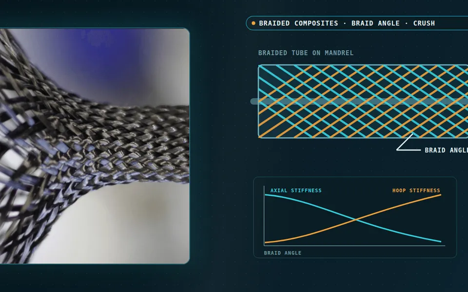
- A composite leg is tuned for stiffness only. In the same paper a laminate chosen for stiffness was too stiff to absorb observable energy when bolts were pulled through it, while a simple two-layer, plus and minus 45 degree plate failed smoothly. The layup is part of the absorber.
- Calibration is called validation. AC 20-146A says refining a model to reduce discrepancies is calibration, and that the FAA will not accept a model validated against another validated model. Validation on tests with no failure or permanent deformation, it adds, gives little confidence in predicting failure, which is what a yielding seat does.
Weight reduction adds pressure. Each member removed from the primary load path, or swapped for a laminate, moves the design point on the diagram above, and AC 20-146A bounds what analysis may substantiate for a changed baseline seat: for a critical member whose baseline ultimate margin of safety is 0.5 or less, the margin may not fall by more than 25 percent. Laminates are calibrated on coupons and elements and validated on subcomponents and components, the building-block approach, as in our article on composite material simulation across scales.
| Question | What the model carries | What it reports | Decision it supports |
|---|---|---|---|
| Forward test: does the seat stay attached? | Pitched and rolled rails, belt, fitting, recorded pulse | Floor loads, permanent deformation, stud tension | Redesign leg, fitting or absorber, or test |
| Downward test: lumbar load | Cushion build-up, seat pan, dummy pelvis and lumbar column | Pelvis-to-lumbar compression against its limit | Cushion and pan changes |
| Row-to-row head and knee strike | Seat pitch, yaw, seat-back break-over, structure ahead, dummy head and knee | Head path, contact place and speed, HIC, femur load | Which seat position and surface to test |
| Which configuration goes on the sled | Places occupied, yaw, track position, anchorage, cushion build-up | The critical case per load path | Sled test plan |
| Lighter or composite change | Validated baseline model with the changed members | Margins and deformation against the baseline test | Analysis route or new dynamic test |
How is aircraft seat crash simulation done properly?
Start from the test. AC 20-146A asks for validation against the original dynamic tests, use only near the conditions validated, and criteria agreed with the authority in a certification plan. As a guide it lists peak floor loads, critical deformation and restraint loads within 10 percent of the test, and for the head a maximum HIC within 100 HIC units and contact velocity within 10 percent. Two tests at the same pulse will likely give different HIC, so an exact match is not realistic.
Verification comes first: code verification, time-step and mesh convergence, and mass scaling that the AC recommends keeping to 5 percent for critical seat components. The virtual dummy belongs in the record; the AC asks that it meet SAE ARP 5765. See our article on crash test dummy simulation.
Uncertainty is usually the missing part. AC 20-146A works one example: a test spread of about ±125 lb in lumbar load gives 95 percent confidence of staying under 1,500 lb only if the measured or simulated load is no greater than 1,430 lb; for HIC the figure is 890. We build that margin into the acceptance logic and sweep material data, friction, belt payout and seat position, so a result is a range. HIC, lumbar load and head path from a dummy model are estimates that depend on material data, fidelity and calibration.
A validated model is not an approved seat
Where does AI help aircraft seat simulation, and where does it not?
- Choosing what to test. Runs over seat position, yaw, occupant placement, anchorage and cushion build-up train a surrogate that ranks the critical cases, the selection AC 20-146A lists for a model used in support of testing. The full model confirms the cases that decide.
- Tuning the structure. A surrogate of the validated model, with a stated range in leg section, layup and absorber load limit, returns stud load and deformation quickly, so the stiffness window is searched, not guessed.
- Calibration and checks. Material and absorber parameters are fitted to coupon, element and component tests by an inverse method that returns a range, and a script flags every run that falls outside the correlation bands you agreed.
It does not replace the validation record. The FAA will not accept a model validated against another validated model, so a surrogate trained on one is a search tool, not evidence. Head contact is a switch, and a surrogate fitted across the line between a head that just clears the next row and one that just touches it smooths over a cliff. AC 20-146A limits extrapolation to conditions similar to those validated; ours stops at the same line and sends the rest to the full model. See AI surrogate models you can sign off.
From one seat study to a seat-crash capability you keep
The return comes when your engineers can put the next seat position, leg section or laminate through the same chain without rebuilding the model.
- Physics model. CFD and FEA set up once, as templates: geometry clean-up, mesh, solver settings and post-processing that every later run reuses.
- Validation. Mesh and time-step studies, and comparison with tests or full-scale data, so the model's uncertainty is known before it is trusted.
- Automated runs. Scripted runs over the parameters and operating conditions that matter, on your hardware or in the cloud.
- AI surrogate. A machine-learning model trained on those runs answers in seconds and says how sure it is; low-confidence questions go back to the solver.
- Decision tool. Optimisation, trade-off charts or operating guidance, in a form your engineers and operators use every day.
- Field data. Test, trial and monitoring data flow back to recalibrate the model, so it improves with every project instead of being rebuilt.
- A seat model template in your explicit solver, Ansys LS-DYNA, Simulia Abaqus, ESI Pam-Crash or Altair RADIOSS, with sled, rails, belts, cushions and dummy interface built in.
- A configuration screen that ranks critical cases for a new seat position, yaw direction or variant.
- A validation record against your baseline dynamic test, with tolerances agreed with your authority or test house before the run.
- A surrogate with a stated range, and a gate that sends anything outside it to the full model.
- Handover and training, so your team runs and extends it. See our training and software development services and the seat design simulation hub.
Questions engineers ask about aircraft seat dynamic tests
What are the 14 g and 16 g seat tests?
Can simulation replace the sled test for an aircraft seat?
Which injury criteria does the dummy model report?
How is a seat model validated against a dynamic test?
Does a lighter or composite seat need a new test?
If a sled slot or a seat redesign is waiting on a model you cannot yet defend, send us the seat family drawing with leg and track layout, the baseline test report, the dummy model you use and the change you are considering. We reply with how we would build the model, the correlation record it should contain and the cases we would run first. Start with a conversation, or read the aerospace seat design capability page.