Ship resistance and propulsion CFD: a digital towing tank for lower fuel use and better CII
Resistance and propulsion set most of a ship's fuel bill. How full-scale CFD, verified and validated against tank tests and trials, finds the savings, and how a trained surrogate keeps finding them in service.
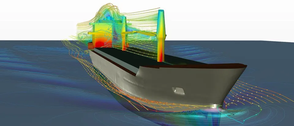
Ship resistance CFD has moved from research tool to commercial necessity. The fuel a ship burns is set first by the resistance of its hull and the efficiency of its propulsion. Under the IMO's EEXI and CII rules, that same physics now decides how the ship is rated.
A towing tank remains the reference for hull performance. But it tests a scale model at a Reynolds number far below the real ship's, and every new variant costs time and money. Computational fluid dynamics can run the full-scale hull, the propeller behind it and the devices around it as often as the design needs. The real question is no longer whether CFD can predict resistance, but how to make its answers trustworthy enough to sign off a design, a retrofit or an operating decision.
Why resistance is now a compliance question
Since 1 January 2023, MARPOL Annex VI has required existing ships to meet the Energy Efficiency Existing Ship Index (EEXI), a one-off technical measure. They also receive an annual operational Carbon Intensity Indicator (CII) rating from A to E. A ship rated D for three consecutive years, or E in a single year, needs an approved corrective action plan. The IMO's guidance on EEXI and CII sets out both.
Both measures come back to the same physics. EEXI depends on the power needed at a reference speed; CII depends on the fuel burnt for the transport work done in service. Lower resistance, better propulsive efficiency and smarter operation all move the numbers, and each can be predicted before steel is cut or a device is bolted on.
Where a ship's resistance comes from
Total resistance is split into components that scale differently between model and ship. That is exactly why the split matters.
- Friction. The boundary layer along the wetted hull. Usually the largest part for slower, fuller ships; it scales with wetted area and Reynolds number.
- Viscous pressure. Flow that thickens and may separate towards the stern, captured by the form factor k and very sensitive to stern shape.
- Wave-making. Energy carried away by the bow and stern wave systems. It rises steeply with Froude number, so it dominates for faster hulls.
- Hull–propeller interaction. The propeller works in the hull's wake and sucks on the hull: wake fraction and thrust deduction decide how much power reaches the water.
- Energy-saving devices. Ducts, pre-swirl fins and rudder bulbs recover rotational and wake losses, and only pay off when assessed behind the real hull.
- Air and appendages. Wind load on the superstructure, rudders, shafts and brackets: small one by one, but they add up and change with loading condition.
- Frictional resistance grows with the wetted surface and depends on the Reynolds number Re = VL/ν. The ITTC-1957 line, CF = 0.075 / (log10Re − 2)2, is the standard reference for it.
- Viscous pressure resistance, expressed through a form factor k, comes from the boundary layer thickening, and sometimes separating, over the aft body.
- Wave-making resistance depends on the Froude number Fr = V/√(gL). It is small for slow, full ships and dominant for fast, slender ones.
- Air and appendage resistance comes from the superstructure, rudder, shaft lines and brackets.
Together they give CT = (1 + k)CF + CW + CAA + CAPP. In a model test, friction is exaggerated because the model's Reynolds number is low, so extrapolating to full scale relies on this decomposition and on correlation allowances. Full-scale CFD avoids much of that by solving the flow at the ship's own Reynolds number, but it brings uncertainties of its own: wall treatment, hull roughness and turbulence modelling.
From towing tank to digital towing tank
A digital towing tank is a set of CFD simulations organised the way a test campaign is. It has resistance, open-water and self-propulsion runs, at model and full scale, across speeds and loading conditions.
| Question | Simulation | What it gives |
|---|---|---|
| How much power at design speed? | Resistance and self-propulsion, RANS with a free surface (VOF) | Delivered power, wake fraction, thrust deduction, propulsive efficiency |
| Is the stern flow clean? | Full-scale RANS with a resolved boundary layer | Nominal and effective wake, separation, inflow to the propeller |
| Will an energy-saving device pay back? | Self-propulsion with and without the device, same mesh strategy | Power difference, with its numerical uncertainty |
| Which trim and draft are best in service? | Systematic runs over speed, draft and trim | A power map for operating guidance |
| Is the hull form right? | Parametric or adjoint shape optimisation | Hull variants ranked on power across the operating profile |
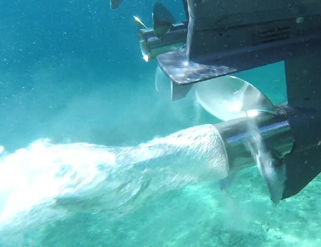
Hull–propeller interaction is where many subtle gains and losses sit. The propeller works in the hull's wake, which helps its efficiency, while its suction lowers the pressure on the stern, which adds resistance. Delivered power follows PD = RTV / ηD, with ηD = ηHηOηR and hull efficiency ηH = (1 − t) / (1 − w). A device that improves one term can quietly worsen another. That is why energy-saving devices must be judged in self-propulsion, behind the hull, never in isolation.
Validating ship resistance CFD before anyone relies on it
A resistance prediction is only useful with an uncertainty attached. The International Towing Tank Conference (ITTC) publishes recommended procedures for exactly this, including the verification and validation of CFD.
- Verification. Systematic grid and time-step refinement, on at least three levels, to estimate the numerical uncertainty of each result.
- Validation. Comparison with model tests, sea trials or published benchmark hulls, with the comparison error judged against the combined numerical and experimental uncertainty.
- Consistency. The same mesh topology, wall treatment and convergence criteria for every variant, so differences between designs are physical and not numerical.
- Scaling. A clear statement of how model-scale results, full-scale CFD and trial data are reconciled, including roughness and fouling.
Small differences need small uncertainties
Where AI changes ship resistance CFD
Each high-fidelity self-propulsion run takes hours of computing. That is fine for checking a design, but far too slow for the questions operators ask every day: which trim for this voyage, at this draft and this speed? It is also too slow for an optimiser exploring hundreds of hull variants.
- Surrogate models trained on a planned set of CFD runs map speed, draft and trim to delivered power in milliseconds, with an uncertainty estimate for every answer. Our article on surrogate models for CFD and FEA explains when they pay off.
- Shape optimisation couples parametric hull models with Gaussian-process or neural surrogates, so the expensive solver is called only where the optimiser needs it. See generative design and optimisation.
- Hybrid models correct a fast physics model with machine learning trained on CFD and on noon reports or sensor data, so the model follows the real ship as it fouls and ages.
The discipline is the same as in any surrogate work. It needs honest bounds on the design space, consistent training data, held-out validation and a route back to the solver when the surrogate is unsure. Our pages on surrogate modelling and reduced-order models and uncertainty quantification describe that approach in more depth.
From one study to a capability you keep
A single simulation campaign answers the question it was asked. The larger return comes when the setup becomes a workflow your own team runs. The next variant, loading condition or operating question then costs hours instead of weeks, and every answer is checked the same way. That is how we build resistance and propulsion work.
- Physics model. CFD and FEA set up once, as templates: geometry clean-up, mesh, solver settings and post-processing that every later run reuses.
- Validation. Mesh and time-step studies, and comparison with tests or full-scale data, so the model's uncertainty is known before it is trusted.
- Automated runs. Scripted runs over the parameters and operating conditions that matter, on your hardware or in the cloud.
- AI surrogate. A machine-learning model trained on those runs answers in seconds and says how sure it is; low-confidence questions go back to the solver.
- Decision tool. Optimisation, trade-off charts or operating guidance, in a form your engineers and operators use every day.
- Field data. Test, trial and monitoring data flow back to recalibrate the model, so it improves with every project instead of being rebuilt.
- Templates for geometry, mesh, solver settings and post-processing, documented so results stay consistent from one variant to the next.
- A validation record that ties the simulations to your tests, trials or field data, with the uncertainty stated.
- Automated runs over the parameters and operating conditions that matter, on your hardware or in the cloud.
- A trained surrogate and a simple decision tool, with the limits of its validity written down.
- Training and handover, so your engineers can extend the workflow themselves. See our training and software development services.
Questions engineers ask about ship resistance CFD
Can CFD replace towing-tank tests?
Model scale or full scale?
How accurate is ship resistance CFD?
What do you need from us to start?
Our hydrodynamics simulation work covers resistance, propulsion, seakeeping and manoeuvring, from hull performance to propulsion and cavitation. If a hull, a retrofit or a CII rating is on your desk, tell us about it.