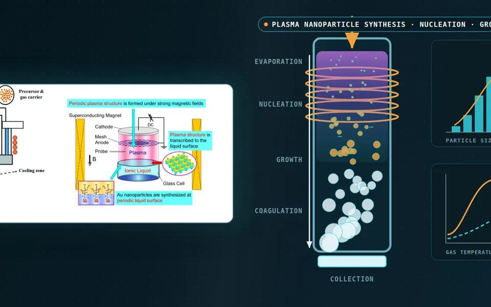
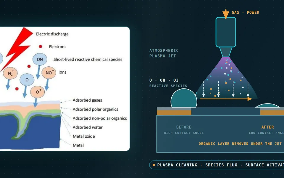
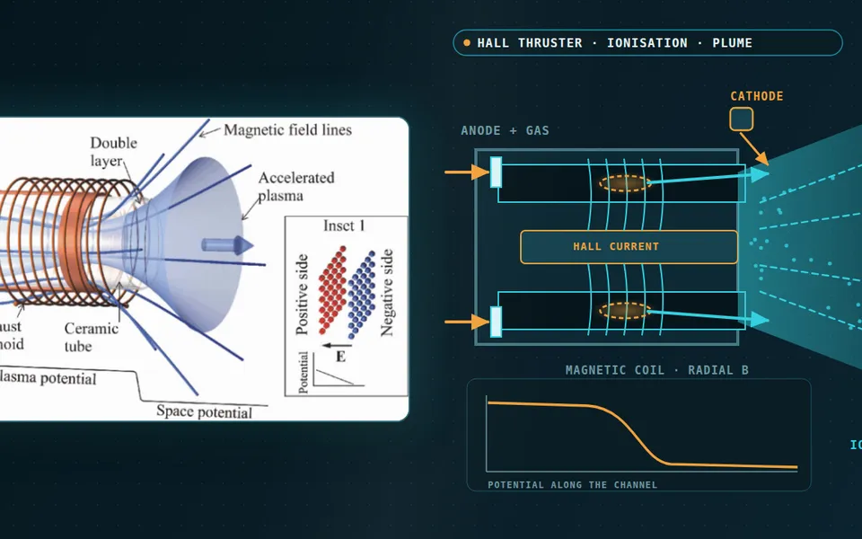
PECVD simulation for film uniformity, stress and chamber clean
The film is thick at the rim, the stress is near the edge of its window and the clean runs long, while the hardware order waits. PECVD simulation couples showerhead flow, the RF discharge and surface chemistry to show which effect sets the profile.
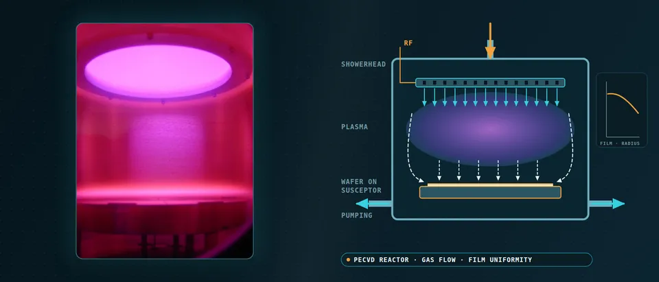
PECVD simulation couples showerhead gas flow and pumping, the capacitively coupled RF discharge and the gas-surface chemistry, so you can trace an edge-thick film, an off-window stress or a long clean to its cause before the next wafer lot. It narrows the options worth running; it does not replace the lot. We build it around your existing solver and film data, with a validation record and a surrogate of stated range.
The new faceplate is drawn, but machining takes weeks and each candidate needs a qualification lot. On the current chamber the SiNx is thick at the rim, the stress sits near the edge of its window, and the same recipe on a second chamber lands elsewhere. Nobody can say whether hole pattern, pumping port, electrode edge or power is responsible, because flow, discharge and surface chemistry move together. The hardware order, recipe release and clean interval wait on the answer.
What must PECVD simulation capture to predict film uniformity?
Four effects are coupled. Gas delivery: the faceplate splits flow into jets and the pump pulls it outward; residence time is pV/Q, with Q the throughput that sccm measures, so pressure and flow are not interchangeable. Discharge: power goes into electrons, and the ion flux to the wafer follows the sheath-edge plasma density times the Bohm speed (kBTe/Mi)1/2. Chemistry: growth is the sum over radicals of sticking probability times arriving flux, over the film’s atomic density. Temperature: susceptor and walls change sticking, film properties and where particles go. Depletion follows the logic of our chemical reactor article.
Each effect can push the profile either way. Kim, Lee and Park (2023) model a showerhead capacitively coupled reactor in two dimensions and find ionisation and excitation peaking near the electrode edge; with helium dilution the edge of the deposition profile rose further when power doubled, with argon it held. In their silicon carbide runs Iliescu and colleagues (2011) saw uniformity worsen at low pressure and suggest a high pumping speed pulling gas to the wafer edge as the cause. On a large high-frequency electrode Eremin (2015) reviews how the electrostatic approximation fails once the mode wavelength nears the electrode radius. A one-factor-at-a-time lot series chases a sum of effects.
- Showerhead jets. Every hole is a small nozzle, so hole pattern and porosity decide how evenly the flow splits and how hard the jets strike the gap. Jin and colleagues describe the faceplate as 20 radial zones, each with its own porosity, and note that symmetric hole patterns tend to leave stagnant flow along their lines of symmetry. Their CFD was inert argon flow: it judges the gas, not the plasma.
- Flow to the pump. The gas turns through the gap, passes the wafer edge and leaves by the pumping ports. Residence time is pV/Q, with Q the throughput that sccm measures, so a change of pressure moves it at fixed flow. In their silicon carbide runs Iliescu and colleagues suggest that at low pressure a high pumping speed pulls the gas to the rim and thickens the film there: a reading of one tool that a flow model can test.
- Discharge and sheaths. RF power goes mainly into electrons, which ionise and dissociate the gas. The ion flux to the wafer follows the plasma density at the sheath edge times the Bohm speed. The dashed lines are the sheath edges, which move with the RF cycle. A fluid model carries this cycle-averaged, with electron-impact rates from a Boltzmann-equation solution, as Kim and colleagues do.
- Radicals, depletion and temperature. Radicals made in the glow are used up on every surface they reach. Where the gas lingers long against the time the precursor takes to be consumed, the rim sees gas already depleted; where flow is fast, the profile follows the flux map. The heated susceptor sets the surface temperature, and Iliescu and colleagues report that deposition rate and stress both move with it.
- Where the field concentrates. Fields crowd at electrode corners, so ionisation and excitation rise there. Kim and colleagues find both peak near the electrode edge, where converging sheaths heat electrons hard, and in their helium case the edge of the deposition profile rose more when power doubled. On a large high-frequency electrode the wave nature of the fields adds a radial voltage pattern that Eremin reviews.
- The profile is a sum. Film thickness adds radial effects whose signs depend on the tool. Flow and depletion can thin the film outward; edge fields and pumping can raise the rim. The dashed curves are two of them, the solid curve their sum, drawn qualitatively. The model computes the real set against your thickness map, and the travelling dot is the sweep over flow, pressure, power and temperature that a surrogate covers.
Which plasma model does a PECVD reactor need: fluid, hybrid, PIC-MCC or electromagnetic?
PECVD often runs at 100 Pa or more, which Kim and colleagues call frequent for silicon films, so the gas is collisional and the reactor is a fluid or hybrid model: compressible flow with species transport, drift-diffusion for charged species and an electron energy equation. Electron-impact rates come from a Boltzmann-equation solution held in a lookup table, the route Kim and colleagues take to keep the two-dimensional run tractable. PIC with Monte Carlo collisions solves the kinetics directly and earns its place on a small domain as the reference for the sheath and the electron energy distribution. One RF period at 13.56 MHz lasts about 74 ns, while gas residence and film growth run far longer, so the reactor model runs cycle-averaged.
Verification is the step most projects skip. Turner and colleagues (2013) had five independently written PIC codes run four helium benchmarks and found implementation uncertainty below 0.5 %; benchmarking also exposed minor errors and a deficient random-number generator. Their accuracy conditions, ωpΔt ≲ 0.2 and λD/Δx ≳ 2, with ωp = (nee²/ε0me)1/2 and λD = (ε0kBTe/nee²)1/2, are the first time-step and mesh checks of any PIC run we set up.
Fluid models fail where kinetics matter. A moment model run on the same benchmarks matched the shape of the ion density but not its peak, by about 50 % in the highest-pressure case, and the PIC results sat roughly a factor of two from experiment, which the authors attribute to omitted physics such as electrode emission and excited states. We calibrate the fluid model to a PIC reference and carry omitted physics as stated uncertainty. Where the electrostatic approximation fails, a Maxwell solver takes the plasma conductivity from the fluid model and returns the radial power pattern; Eremin lists shaped electrodes, graded-conductivity coatings and segmented, phase-controlled feeds as remedies.
How trustworthy is the chemistry set, and what decides film stress?
The reaction set is the largest uncertainty. The silane set of Kim and colleagues runs up to Si5H12 with literature rate coefficients, and their sticking probabilities come from other groups’ experiments. Changing the diluent from helium to argon changed the modelled profile, so a set tuned for one recipe does not transfer unchecked. We keep each set as a record with sources and a range, sweep the range, and report which reactions the profile is sensitive to. The record extends to SiO2 and a-Si; see our detailed chemistry page.
Stress follows ion bombardment and composition, and frequency is the lever. Iliescu and colleagues found silicon nitride deposited at 13.56 MHz tensile and at 380 kHz compressive from ion densification, with alternating or combined operation reaching near-zero stress; pressure, power and substrate temperature moved stress too. Simulation supplies ion flux, energy and radical ratios at each radius; stress comes from a property model calibrated on your measured stress, with its range stated.
What can simulation say about chamber clean, cold spots and particles?
Clean runs the film backwards, so it reads the same record. Huang and colleagues (2018) note that NF3 serves remote plasma sources because it yields fluorine atoms, the main etchants of silicon-containing materials. In their model of a remote Ar/NF3/O2 source feeding a chamber with a nitride-coated wafer, silicon sites leave as volatile SiF4 and nitrogen sites by NO and N atoms; with fluorine-rich flux the rate is limited by NO and N. We map etchant flux to every surface, so the slowest-clearing surface sets the interval; an in-situ clean needs its own source model.
Particles are a chemistry and a thermal problem. Husmann and colleagues (2023) call particles below 10 nm killer defects, record that the usual remedy, less plasma power, costs rate and gas utilisation, and list flow sweeping, thermophoresis away from a hotter substrate, pulsing and hydrogen dilution as other levers. Radical diffusion to sink surfaces plays a major role in whether film or particles form, and wall sticking changes as walls are heated, bombarded and coated. So wall state is a drifting parameter, and because thermophoresis moves particles away from hot surfaces, the temperature field, cold spots included, belongs in the same conjugate model.
- Electron heating at the sheath edges. The sheath edges move with the RF cycle and electrons are heated there before they ionise and dissociate the gas. At PECVD pressures a fluid model carries the reactor; PIC with Monte Carlo collisions on a small domain is the reference for the electron energy distribution. Turner and colleagues show five independent PIC codes agreeing within stated bounds in helium, in one dimension.
- Dissociation into radicals. Electron impact, and excited atoms of the diluent, break silane into SiH3, SiH2 and hydrogen; radicals then add to silane to make disilane and higher silanes. The gas-phase set of Kim and colleagues runs up to Si5H12 with literature rate coefficients, and in their model the disilane level differed about tenfold between argon and helium dilution.
- Sticking and film growth. Radicals that reach the surface stick with a probability that depends on the species. Growth is the sum over radicals of sticking probability times arriving flux, divided by the film's atomic density. Kim and colleagues take the sticking probabilities from other groups' experiments and use density-functional calculations for disilane: inputs with a range, not results.
- Ion bombardment sets stress. Ions fall through the sheath onto the film. Iliescu and colleagues explain why frequency matters: at 13.56 MHz only electrons follow the field and their nitride came out tensile, while at 380 kHz stronger ion bombardment densified it into compression; alternating the two gave near-zero stress. The model supplies ion flux and energy, and stress comes from calibration on your measured stress.
- From disilane to particles. Higher silanes grow into clusters, which collect electrons faster than ions and charge negatively. Husmann and colleagues call particles below 10 nm killer defects, note that cutting power is the usual remedy at the cost of rate and gas utilisation, and list sweeping flow, thermophoresis away from a hot substrate, pulsing and hydrogen dilution as further levers.
- The clean step reverses the film. NF3 gives fluorine atoms, the main etchants of silicon-containing materials such as SiO2, SiC and Si3N4 (Huang and colleagues). In their remote-plasma model nitride goes by removing Si sites as volatile SiF4 and N sites by NO and N atoms, and with fluorine-rich flux the rate is limited by NO and N. The fading wall layer is the deposit: the surface that clears last sets the clean time.
- What the model has to carry. The electron energy distribution that sets every rate, the reaction set with its range, the sticking probabilities and the wall state. Wall sticking changes as walls are heated, bombarded and coated, Husmann and colleagues note, so it is a state, not a constant. We hold all four as ranges in one record, and every question above reads that record.
Which PECVD question needs which model?
| Question | Model | Reports | Limit to state |
|---|---|---|---|
| Which faceplate pattern gives even flow? | CFD, faceplate as porous zones, no plasma | Flow spread above the wafer | Flow is a proxy for film |
| Why is the rim thick or thin? | 2D fluid plasma with chemistry and flow | Radical and ion flux maps, profile | Reaction set with a range |
| What ion energy reaches the wafer? | Sheath model, PIC-MCC reference | Ion flux and energy distribution | Stress needs your calibration |
| Does a large or VHF electrode light unevenly? | Maxwell solver with fluid-model plasma | Radial voltage and power pattern | Valid where the plasma model is |
| How long should the clean run? | Chemistry, thermal model, wall state | Etchant flux per surface | Wall sticking drifts with use |
| Which settings reach the target window? | Surrogate on designed runs | Thickness, uniformity, stress maps | Gate to the full model |
A simulated profile is not a qualified process
Where does AI help PECVD design, and where does it not?
Jin and colleagues (2024) parametrised a showerhead faceplate in 20 radial porosity zones, ran each CFD case in about ten minutes on a desktop and trained surrogates that predict in about a millisecond. A Bayesian optimiser, which feeds each proposed design back to the CFD, reached competitive designs with a tenth of the data points the surrogate-only searches used; the best designs gained about 10 % in flow uniformity. Two cautions from the paper: the CFD was argon flow with no plasma, and uniformity was the velocity spread 1.5 mm above the pedestal, a proxy for film.
- Surrogates over the operating window. Trained on designed runs of the full chain over flow, pressure, power and susceptor temperature, a surrogate returns thickness profile, uniformity and ion-flux maps in seconds inside a stated range, with a gate to the full model.
- Calibration. An inverse fit to your thickness and stress maps returns ranges for sticking and rate parameters.
- Drift. A wall-state parameter updated from your maintenance and particle records flags when a recipe has left the calibrated range.
It does not repair a wrong reaction set, extrapolate past its sampled range or stand in for the wafer lot. See our surrogate modelling, hybrid physics-AI and uncertainty quantification pages and our articles on surrogate models and validating them.
From one chamber study to a PECVD workflow you keep
The return comes when your engineers can put the next faceplate, recipe or chamber through the same chain.
- Physics model. CFD and FEA set up once, as templates: geometry clean-up, mesh, solver settings and post-processing that every later run reuses.
- Validation. Mesh and time-step studies, and comparison with tests or full-scale data, so the model's uncertainty is known before it is trusted.
- Automated runs. Scripted runs over the parameters and operating conditions that matter, on your hardware or in the cloud.
- AI surrogate. A machine-learning model trained on those runs answers in seconds and says how sure it is; low-confidence questions go back to the solver.
- Decision tool. Optimisation, trade-off charts or operating guidance, in a form your engineers and operators use every day.
- Field data. Test, trial and monitoring data flow back to recalibrate the model, so it improves with every project instead of being rebuilt.
- A parametric chamber template in your existing solver: faceplate zones, gap, pump port, electrode edge and susceptor temperature as parameters, with one record of mesh, time-step and model choices.
- A reaction-set library with sources, ranges and an out-of-range map.
- A validation record against your thickness, stress or refractive-index maps and your clean and particle data, tolerances set before the run.
- An electromagnetic and thermal exchange on the same geometry: electromagnetic multiphysics and thermal analysis.
- A surrogate with a stated range and a gate to the full model.
- Handover and training, so your team runs and extends it: training and software development.
Questions engineers ask about PECVD simulation
Can PECVD simulation predict film thickness uniformity?
Do I need PIC for a PECVD reactor?
Can it predict film stress?
Can it shorten a chamber clean?
Does it replace a qualification lot or a gas-safety review?
If a faceplate order, a recipe transfer or a clean interval is waiting on this, send us the chamber drawing with hole map and pump port, the gas, flow, pressure, power, frequency and susceptor-temperature window, the thickness, stress or refractive-index maps you have, and your clean recipe and particle records. We reply with the model chain we would set up, the validation we would run and what a surrogate could cover. Start with a conversation, or see our PECVD page.