Battery thermal runaway propagation simulation: showing that one failed cell does not become a pack fire
UN R100 and China's GB 38031 now ask pack designers to show what happens when one cell fails. How calibrated CFD and FEA predict propagation, where AI helps, and why simulation supports certification testing rather than replacing it.
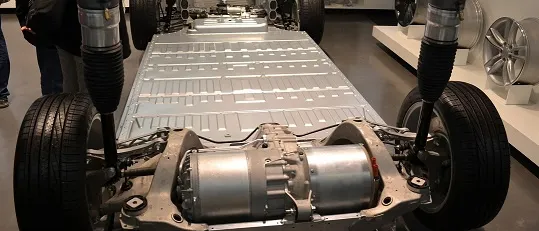
Thermal runaway propagation simulation predicts whether one failing cell passes enough heat and hot gas to its neighbours to turn a single-cell event into a pack fire, and how long that takes. Pack designers now have to show it: UN Regulation No. 100 and the Chinese standard GB 38031 both set requirements on what a single failed cell may do.
The physical test that proves the answer is destructive, slow and expensive, and it arrives when the pack is nearly frozen. A barrier that is too thin, a vent that points the wrong way or a busbar that carries heat down the row then costs weight, volume and range to fix. Simulation lets you ask those questions while the design can still change, if it is calibrated against abuse-test data and honest about its limits.
What do regulations actually require for thermal propagation?
- UN Regulation No. 100. The 05 series, in force from 26 September 2025, covers propagation triggered by an internal short circuit leading to single-cell thermal runaway. In the text reproduced in UN Regulation No. 100 (05 series of amendments), as reproduced in Commission Regulation (EU) 2026/1695, the system must warn the occupants. For five minutes after the warning signal, no fire, explosion or smoke may reach the passenger compartment. The requirement is also deemed met if the single-cell runaway does not propagate within two hours.
- How it is verified. By a physical test (Annex 9K, starting with localised fast external heating) or, where testing would compromise the design, by a documented risk-management analysis. That analysis may use testing, analysis, simulation, models, scientific papers and field data, alone or combined (paragraph 6.15.4.3).
- UN GTR No. 20. As incorporated into US law in NHTSA's FMVSS No. 305a final rule, it takes a documentation approach to propagation from a single-cell internal short circuit, not a performance test.
- China, GB 38031. The 2020 edition asked for a thermal event warning five minutes before fire or explosion. According to the report on the new GB 38031-2025 standard on the Chinese government portal, GB 38031-2025, effective 1 July 2026, moves to no fire and no explosion (with the alarm still required), and smoke that does not endanger occupants.
The requirements differ in form and transition dates, so read the current text for each market you sell into.
Why is thermal runaway propagation hard to simulate?
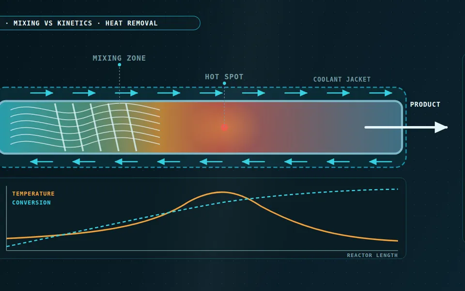
A cell in runaway is a chemical reactor in a sealed can. The review by Feng et al., “Thermal runaway mechanism of lithium ion battery for electric vehicles: A review” (Energy Storage Materials, 2018) describes the sequence: decomposition of the SEI layer, reaction of the anode with the electrolyte, separator collapse and internal short circuit, cathode decomposition, then electrolyte venting and often combustion. Each stage is thermally activated, so its heat release follows an Arrhenius law, dαi/dt = Ai exp(−Ei/RT) f(αi), and the heat added to the cell is the sum of those terms.
- Abuse heating and SEI decomposition. An external or internal trigger warms the cell until the first exothermic reaction, decomposition of the SEI layer, starts to add heat.
- Onset. Self-heating overtakes heat loss. Accelerating rate calorimetry measures this point under near-adiabatic conditions; in a pack it depends on the surroundings.
- Anode reaction and separator collapse. Reactions between the lithiated anode and the electrolyte grow; when the separator fails, an internal short adds electrical energy as heat.
- Cathode decomposition and venting. The largest heat release, with gas generation, venting and possible combustion. This is the source of the vent-jet CFD problem.
- Neighbouring cell. The same sequence, started later: it is heated by conduction, hot gas and ejecta from the first cell.
- Propagation delay. The time between the two onsets. Barriers, spacing, cooling and venting paths are the levers that stretch it.
- Escape time. The window between the first cell's event, or the warning it triggers, and a hazard at pack level. Occupant-protection requirements are written around it.
- Heat generation against heat loss. The balance behind everything above. Runaway follows when generation exceeds loss and also grows faster with temperature.
Whether a cell reaches onset depends on a balance. Runaway follows when heat generation exceeds heat loss and also rises faster with temperature (the Semenov condition). The same cell can survive in a cold, well-cooled pack and run away in a tight, hot one, so propagation is a property of the design and not of the cell alone. Lumped Arrhenius models of this kind are described in Hatchard et al., “Thermal Model of Cylindrical and Prismatic Lithium-Ion Cells” (J. Electrochem. Soc., 2001), and Feng et al. (Applied Energy, 2015) applied a propagation model to a pack of large-format NCM cells to design a safer layout.
How does heat and gas get from one cell to the next?
- Trigger cell. Exothermic reactions inside the failing cell release heat faster than it can leave. This is the source term of the model, built from Arrhenius kinetics and calibrated from calorimetry and abuse tests.
- Cell-to-cell conduction. Heat crosses the cell wall, a thin contact gap and the barrier. Contact resistance and compression, not just material conductivity, set how much gets through.
- Thermal barrier. Mica, aerogel or intumescent layers. Their conductivity changes with temperature and compression as cells swell, so it has to be measured under load.
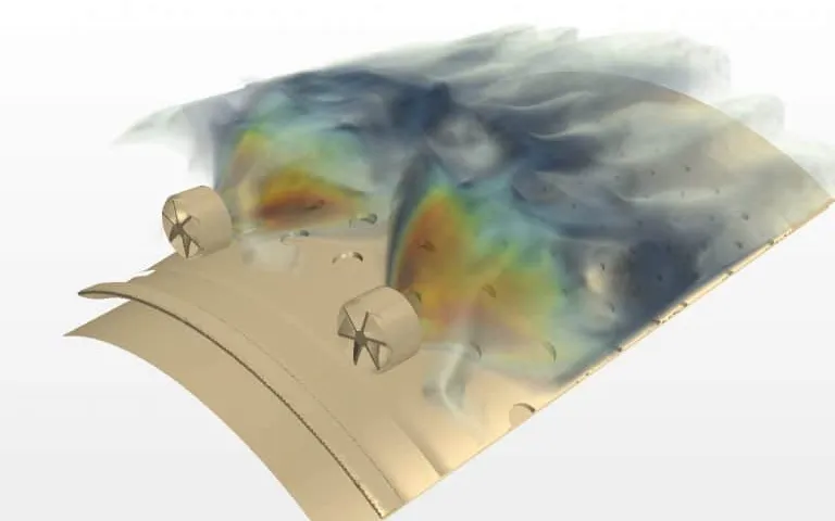
- Vent jet. Hot, flammable gas and solid particles leave the cell through its vent. This is a compressible, multi-species, particle-laden flow, and it can ignite.
- Busbars and hot gas. Gas and ejecta land on busbars and neighbouring terminals; the busbar itself conducts heat along the row and can be short-circuited by conductive debris.
- Cooling plate. The main heat sink. It slows propagation but is limited by interface resistance and by whatever coolant is still flowing.
- Vent port. Where the gas leaves the pack. Its position and size decide whether smoke is routed away from the cabin or finds its own way out.
- Neighbour cell. The next cell propagates if the heat it receives drives it to its own onset before the heat can be removed.
- Conduction through the cell wall, contact gaps and the barrier. Contact resistance is often as important as the barrier's own conductivity.
- Barriers such as mica, aerogel and intumescent layers. Conductivity changes with temperature, and with compression as cells swell, so values measured cold and unloaded mislead.
- Vent gas and particles. The jet is compressible, multi-species and particle-laden, can burn at the vent, and carries hot ejecta onto neighbours and busbars.
- Busbars and enclosure. Metal carries heat along the row; enclosure, plate and gas path form one conjugate heat-transfer problem.
- Electrical coupling. In parallel groups a failed cell can be driven by its neighbours, so the electrical network belongs in the model.
Why is a test-only approach so expensive?
Each propagation test consumes a pack or module and gives one outcome. Trigger position, state of charge, ageing and set-up all change the result, so a single pass says little about margin. Barrier thickness, cell spacing, vent location and cooling layout interact, and the cheap moment to change them is before tooling, not after the test.
Which simulation level answers which question?
| Question | Model | Needs, and main limit |
|---|---|---|
| Which barrier and spacing stop conduction? | Thermal network or 3D FEA with kinetic heat source | Calibrated kinetics, barrier properties under compression and temperature, contact resistance; gas effects are lumped |
| How does heat spread through a module with cooling? | 3D conjugate heat transfer (thermal analysis) | Cell, busbar, plate and coolant geometry; cost grows with cell count |
| Where does the vent gas go, and what does it heat? | Compressible, multi-species CFD with particles, optionally with combustion | Vent mass flow, composition and particle data from tests; sources are measured, not predicted |
| How do electrical and thermal events interact? | Coupled electro-thermal network | Cell and busbar resistances, string layout; internal short behaviour is poorly known |
| Which layout meets the target at least mass and cost? | Surrogate over validated runs | A planned set of runs and a stated design range; valid only inside it |
No one level does everything. The practical route is a hierarchy: kinetics calibrated at cell level, a fast model for many layouts, and CFD where gas flow decides.
How do you calibrate a propagation model?
Cell kinetics come from calorimetry. Accelerating rate calorimetry (ARC) gives self-heating onset and the temperature history under near-adiabatic conditions; differential scanning calorimetry gives material-level reactions. Cell and module abuse tests then give what the kinetics cannot: vent timing, gas release and the neighbour's response. Module and pack test results are kept back, so the final comparison is made against data the model has not seen.
A propagation model is only as good as its abuse-test calibration
Where does AI help with thermal runaway propagation simulation?
- Bayesian calibration. Priors come from the literature and DSC; the likelihood compares predicted and measured ARC and abuse-test curves. The posterior shows which parameters the data really pin down. Activation energy and pre-exponential factor are strongly correlated, so individual values are often poorly identified while their combined effect is not. Posterior samples pushed through the pack model give a distribution of propagation times, and margin is stated as a distribution, not one number. See our work on uncertainty quantification.
- Surrogates for trade-offs. A planned set of runs over layout, barrier thickness and vent geometry trains a surrogate that predicts propagation delay and peak temperatures in seconds. Pairing it with mass and cost gives a Pareto front of safety margin against weight, volume and money. Our article on surrogate models for CFD and FEA and the surrogate modelling page cover the method.
- An out-of-range gate. Every query is checked against the training range and the surrogate's own uncertainty. A new cell chemistry, a barrier outside the tested range or a prediction near the pass/fail edge goes back to the full solver instead of being answered.
- An automated cell-to-module-to-pack template. One parametric description builds the cell model, the module and the pack with the same boundary conditions and mesh strategy, so the next layout is a parameter change, not a rebuild.
Where AI does not help: it cannot extrapolate beyond calibrated physics, and it should predict continuous quantities such as times and temperatures, not a binary pass or fail. That is a decision made with the margin on the table.
What does a permanent propagation workflow look like?
A single study answers one pack. A workflow answers the next one. We consult to diagnose, build custom workflow tools and surrogates, and train your engineers to own the result.
- Physics model. CFD and FEA set up once, as templates: geometry clean-up, mesh, solver settings and post-processing that every later run reuses.
- Validation. Mesh and time-step studies, and comparison with tests or full-scale data, so the model's uncertainty is known before it is trusted.
- Automated runs. Scripted runs over the parameters and operating conditions that matter, on your hardware or in the cloud.
- AI surrogate. A machine-learning model trained on those runs answers in seconds and says how sure it is; low-confidence questions go back to the solver.
- Decision tool. Optimisation, trade-off charts or operating guidance, in a form your engineers and operators use every day.
- Field data. Test, trial and monitoring data flow back to recalibrate the model, so it improves with every project instead of being rebuilt.
- Templates for cell, module and pack models, with documented boundary conditions and post-processing.
- A validation record tying every model to the calorimetry and abuse tests that calibrated it, with the data used for tuning kept apart from the data used for checking.
- Automated runs over layout, barrier and vent parameters, on your hardware or in the cloud.
- A trained surrogate with its validity range and out-of-range gate written down.
- Training and handover, so your team can add a new cell or barrier. See training and software development.
It sits alongside the cooling work in our EV thermal management simulation article and our automotive engineering practice.
Questions engineers ask about thermal runaway propagation
Does thermal runaway in one cell always spread to the rest of the pack?
Can simulation replace the thermal propagation test?
What data do you need to calibrate a model?
Which barrier is best: mica, aerogel or intumescent?
How do UN R100 and GB 38031 differ?
If a pack layout, a barrier decision or a propagation test plan is on your desk, send us the cell datasheet, any ARC or abuse data, a pack drawing and the decision you need to make. You get back a scoped plan: what to calibrate, what to model, what the results will and will not support, and what stays with the physical test.