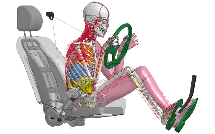
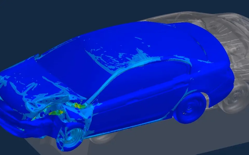
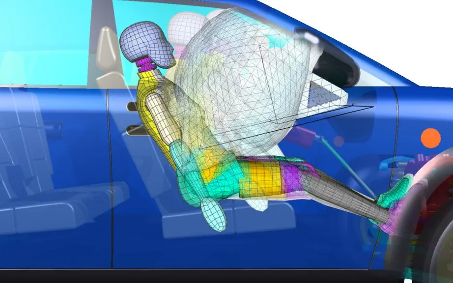
EV battery pack crash simulation for side pole, underbody and intrusion load cases
The pack is the heaviest part under the floor and the costliest to damage. Crash simulation shows how side pole, barrier and underbody loads travel into it, so protection goes where it earns its mass, before the first pack is crushed.
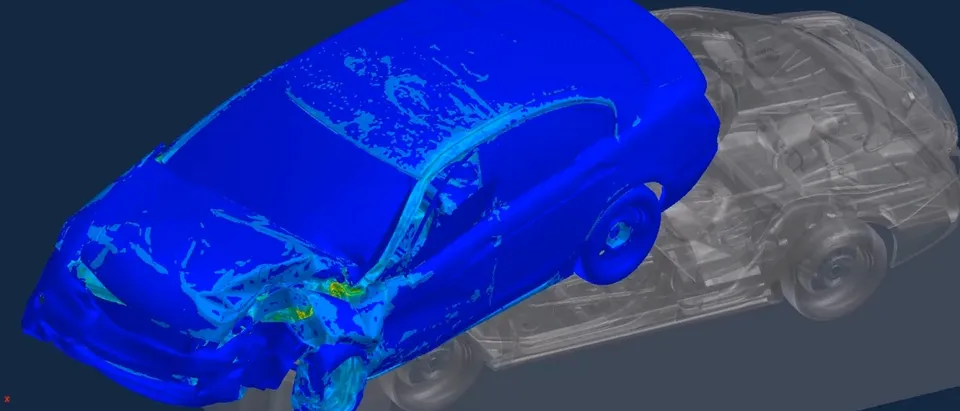
Battery pack crash simulation predicts how crash loads travel from the vehicle structure into an EV pack, where the enclosure, frame and modules deform, and whether the cells are loaded enough to be damaged. We build it as a workflow in your existing crash solver, so the answer is ready for every design change, before the pack is built and before the sled or crash test.
The pack is the heaviest part under the floor and the most expensive to damage. At the design review the structures team asks for a thicker sill, packaging wants that volume back for cells, and the battery team wants a stiffer shield for ground strikes. Each change costs mass, range or money, and every physical pack sacrificed to settle the argument is one the next build cannot use. Which load case actually drives the structure decides which change is worth paying for.
What does battery pack crash simulation have to answer?
Four questions, in order. Does the pack stay attached and out of the cabin? Does the pack structure carry the load, or does it reach the cells? Are the cells deformed enough to be damaged? Is the high-voltage system in a safe electrical state afterwards? Regulations ask versions of the same four.
At vehicle level the crash is an energy balance. The kinetic energy at impact, ½ m v2, ends up as internal energy in crushed structure. In an explicit model, Ekinetic + Einternal + Econtact + Ehourglass equals the initial energy to within a small drift, and that drift is the first check on any result. The pack enters the balance twice: its mass sits in m, and its stiffness decides whether the energy is absorbed in the sill, in the pack frame or in neither.
A cell crushed enough to short internally becomes a thermal problem, covered in our thermal runaway propagation article. Here we stop at the mechanical state that starts it.
Which crash scenarios load an EV pack, and what do the texts say?
Our crash scenarios list runs from frontal, side and pole impact to rear impact and rollover. For an EV each is a different question about the pack. We quote only what we read in the sources.
FMVSS No. 305a is mandatory for vehicles from 1 September 2027; FMVSS No. 305a (49 CFR 571.305a) is the text, and FMVSS No. 305 applies before that date. A light vehicle is subject to any one barrier test, then a static rollover. The frontal test runs at up to 48 km/h, perpendicular or up to 30 degrees off. The rear moving barrier runs between 79 and 81 km/h, the side moving deformable barrier between 52.0 and 54.0 km/h, and the rollover is in successive 90 degree increments. There must be no evidence of fire or explosion from impact until one hour after the sequence, the energy storage device must stay attached and out of the occupant compartment, and no more than 5.0 litres of electrolyte may leak.
The pole is not in that sequence. FMVSS No. 214 sets a vehicle-to-pole test into a rigid pole 254 mm in diameter at up to 32 km/h, with the vehicle moving at 75 degrees (±3) to its centreline. The narrow contact loads a short length of sill and door, the structure beside the pack edge.
UN Regulation No. 100, 05 series of amendments, in force from 26 September 2025 (consolidated text published in the EU Official Journal as 2026/1695), tests the pack itself. For mechanical shock the manufacturer may use vehicle crash tests under UN Regulations Nos. 94, 95 and 137, or a component test with the acceleration corridors of Annex 9C. For mechanical integrity, which applies to packs for categories M1 and N1, Annex 9D crushes the pack with a force of at least 100 kN and not more than 105 kN. The same clause lets the manufacturer replace that figure with a value declared from actual crash tests or from simulation, with the forces agreed by the Technical Service.
Underbody impact has no line in the texts we read. Kerb strike, road debris and grounding on a ramp are load cases your programme defines.
- Pole or barrier. A rigid, narrow object moving sideways into the vehicle. Because the contact is narrow, the load is concentrated on a short length of sill and door. A wider barrier spreads the same energy over more structure, so the two scenarios are modelled separately.
- Sill as the crush zone. The first structure to take the load. Its section is designed to fold in a controlled way and absorb energy before the load reaches the pack. How far it folds, and when it stops folding, sets the intrusion the pack sees.
- Load path in the pack frame. Once the sill is loaded, force passes into the pack through its side frame and along the top and bottom rails to the far sill. The aim is a path that carries the load around the cells, with the enclosure stiff enough that it does not buckle onto them.
- Cross members. Internal members that tie the two sides of the pack together and share load between them. Their number and position change where the frame bends, so they are the first design variables in a pack-protection study.
- Cell modules. The protected volume. Intrusion that stays outside it is a deformation; intrusion that reaches it is a question for the cell-level model, because the damage criterion belongs to the cell, not to the enclosure.
- Underbody shield and ground strike. A second load case from below: an obstacle presses on the shield, which spreads the contact over the pack floor. The shield can tear, or deflect into the pack, and no barrier test in the regulation texts we read covers this, so your programme defines it.
| Load case | What it loads in the pack | What the text we read asks | What the model must resolve |
|---|---|---|---|
| Frontal barrier | Front edge, mounts, front cross member | FMVSS 305a: up to 48 km/h, up to 30 degrees | Front collapse before the pack is loaded |
| Side moving barrier | Sill, pack side frame, first module | FMVSS 305a: 52.0 to 54.0 km/h | How sill and pack frame share the load |
| Side pole | A short length of sill and pack edge | FMVSS 214: 254 mm pole, up to 32 km/h, 75 degrees (±3); not in the 305a sequence | Peak local intrusion at the pack edge |
| Rear barrier | Rear edge and mounts | FMVSS 305a: 79 to 81 km/h | Rear structure and mounts |
| Static rollover after impact | Enclosure, seals, module fixings | FMVSS 305a: successive 90 degree increments | Leak paths in a damaged pack |
| Underbody strike | Shield and pack floor | No clause in the texts we read; your programme defines it | Shield tearing and floor intrusion |
| Component crush | The whole pack, in two horizontal directions | UN R100 Annex 9D: 100 to 105 kN, or a value declared from crash tests or simulation | The force the vehicle model delivers |
| Component shock | Modules and internal mounts | UN R100 Annex 9C: acceleration corridors | The pulse at the pack mounts |
Why is a battery pack hard to model in a crash?
Scale is the first difficulty: a cell is a stack of very thin layers, a pack is metres across. The cell is a layered composite whose compression response differs from its tension response, and an internal short follows separator failure, not plastic strain of the can. It needs a constitutive model and a damage indicator calibrated on cell tests; the material card that fits the enclosure does not transfer.
The enclosure adds welds, adhesive and bolts that fail locally, and extrusions and castings whose fracture model, calibrated at one element size, mispredicts at another. Contact penalty stiffness, initial penetration and friction between sill, pack and shield each move the load path.
Time-step control adds a trap. The explicit stable step is bounded by Δt ≤ Le / c, with c = √(E/ρ) and Le the element length. Thin cell layers and small fasteners cut Δt, and mass scaling restores it by adding mass. A pack is a large share of the vehicle's mass, so mass added to it shifts the energy balance and the load path. We bound the added mass and report it beside every run.
Where does the usual pack-crash workflow break?
The vehicle crash team usually carries the pack as a lumped mass in a stiff shell, because the cell detail is not theirs. The battery team models cells and modules under a prescribed pulse, because the vehicle is not theirs. The force the vehicle model reports is wrong if the pack is too stiff or too soft, and the pulse the cell team applies is wrong if it came from last release. Each hand-off is a spreadsheet, and each body release invalidates it. A crushed pack is a pack gone, and a finding after release is a tool change on a cast or extruded enclosure.
How do you simulate pack protection properly, and where does AI help?
- Calibrate the pack in the vehicle model. A component crush test gives a force-intrusion curve, and the vehicle model's pack is tuned to it, so the load shared by sill and pack is credible. A rigid block cannot do this.
- Drive a pack submodel from the vehicle run. Recorded motion and forces at the pack boundary load a fine model of enclosure, joints and cross members.
- Go down to the module and cell. The deformation field loads a module model, and the calibrated damage indicator says whether the loading is enough to start a short circuit.
- Verify, validate, bound. Energy balance, added mass, mesh and contact studies; a component crush or shock test; a spread over impact position, speed and material scatter. See building a credible explicit model.
- Vehicle level. The full crash model, run in your existing crash solver. It supplies what the pack is subjected to: intrusion, interface forces and the pulse at the pack mounts, for every scenario in the list. Its pack is calibrated, not a rigid block.
- Pack level. The pack structure, in finer detail than the vehicle model allows: enclosure, frame, joints, cross members and the modules as blocks. This is where fracture of extrusions, welds and adhesive is resolved and where design changes are tried.
- Module level. Cells in their housing, with the compression the structure delivers to them. This level tells you which cells are loaded and how, and whether the module frame protects the next one.
- Cell level. A layered winding or stack, calibrated on cell indentation and compression tests. It carries the damage indicator that says whether the loading is enough to start an internal short circuit. The thermal consequences are a separate model.
- Motion and forces, downward. Each smaller model is driven by the recorded motion and forces of the larger one at its boundary. Rerunning the vehicle model for a new body release rewrites the input to the others, so the hand-off is automated, not typed in.
- Evidence, upward. Every level has its own check against a test: a vehicle or sled test, a pack or sub-pack crush or shock test, a cell indentation test. The record of what each model has been compared with, and its range, travels with the numbers.
Machine learning earns its place in the repeated part of this work:
- Design-space surrogates. A surrogate trained on automated explicit runs over sill section, cross-member layout, shield thickness and mount stiffness returns intrusion at defined points and the mass change for a candidate without a new run. See surrogate models for CFD and FEA.
- Optimisation on a budget. Bayesian optimisation over the same variables maps mass against intrusion within a fixed budget of full runs.
- Run-quality gates. A classifier flags runs with a failing energy balance, excess added mass or initial penetration before they enter the training set.
It does not supply the cell physics: that criterion comes from cell tests, not from intrusion data. A surrogate also has a range, and a cross-member layout it has never seen goes back to the full model. See AI surrogate models you can sign off.
Do not hand a pack test a force from a model that has not seen the pack
From one pack study to pack protection your team can rerun
The value comes when the next body release, cell format or pole position is a rerun, not a project.
- Physics model. CFD and FEA set up once, as templates: geometry clean-up, mesh, solver settings and post-processing that every later run reuses.
- Validation. Mesh and time-step studies, and comparison with tests or full-scale data, so the model's uncertainty is known before it is trusted.
- Automated runs. Scripted runs over the parameters and operating conditions that matter, on your hardware or in the cloud.
- AI surrogate. A machine-learning model trained on those runs answers in seconds and says how sure it is; low-confidence questions go back to the solver.
- Decision tool. Optimisation, trade-off charts or operating guidance, in a form your engineers and operators use every day.
- Field data. Test, trial and monitoring data flow back to recalibrate the model, so it improves with every project instead of being rebuilt.
- A scenario library in your existing solver: frontal, rear, side barrier, side pole, rollover and underbody strike, with parameters, post-processing and pass-fail sheets scripted.
- A calibrated pack and cell model, with the tests it was fitted to and the range of loading it covers.
- Automated hand-off from the vehicle run to the pack submodel, so a new body release rewrites the pack loading without a retyped pulse.
- A model quality record: energy balance, added mass, contact and mesh checks stored beside every result.
- A surrogate with a stated range over sill section, cross-member layout, shield thickness and mount stiffness, with a gate to the full model.
- Handover and training, so your engineers extend it themselves. See our training and software development services.
Questions engineers ask about battery pack crash simulation
How do you simulate an EV battery pack in a crash?
Why does the side pole case matter for the pack?
Can simulation replace the battery crush test?
What about thermal runaway after a crash?
If a pack-protection decision is on your table, send us the pack outline and mount positions, the sill and floor sections, the load cases your programme adds to the regulatory list, the crash model you run today, and any crush or cell indentation tests you hold. We will reply with which load cases look likely to drive the pack structure, how we would calibrate and validate the model, and what range a first surrogate could cover. Start with a conversation, or read about our crash test simulation work.