EV road noise simulation, from tyre cavity and suspension to the cabin
In an electric or hybrid vehicle nothing masks the road. A checked chain from the tyre and its air cavity through bushes and body panels to the occupant's ear ranks the paths before the floor and subframe are frozen.
EV road noise simulation predicts the sound at the occupant's ear by following tyre and road excitation through the tyre and its air cavity, the suspension and its bushes, and the body panels and cabin air, and it ranks those paths so the right one is treated first. We build the chain around your existing multibody, finite element and acoustic solvers, so tyre, bush and floor decisions are made before the subframe tooling is cut and the body structure is frozen.
A pre-series prototype clears its motor and gearbox reviews, meets a coarse-chip surface and the cabin fills with a drone that follows the road, not the pedal. Nothing has become louder; nothing is left to hide it. The review has to say which path carries it, what it costs to fix on this platform, and whether the answer holds on the next tyre nomination. The options on the table are a bush retune, a subframe change, damping mass that costs range, or a different tyre.
Why is road noise louder in electric and hybrid vehicles?
It is not louder. It is unmasked. Hua, Thomas and Shultis, in their 2021 review of battery electric vehicle NVH in Science Progress note that without an internal combustion engine previously masked noises become audible, and that road noise, transmitted from the tyre through the suspension to the cabin, becomes one of the factors that most affects product quality. SAE paper 2026-26-0351 on low frequency interior noise from tyre-road interaction makes the same point for the low frequency structure-borne range that engine noise used to cover.
A hybrid has both states. With the engine off it behaves as an electric vehicle; with it running, the floor of masking noise returns, and the driver hears the road change when the engine starts or stops. Targets therefore belong to each powertrain state, not to one average. Motor and gear tones are a separate subject, covered in our electric motor NVH article.
- Masking floor. A running engine fills the cabin with broadband sound that hides much of what the road produces. With an electric drive the floor drops, and the same road noise sits above it. In a hybrid the floor moves each time the engine starts or stops.
- Structure-borne road noise. Vibration carried from the tyre through the suspension into the body. In the paper cited in the article it dominates at low frequency and low speed, and it is the part an electric drive uncovers first.
- Tyre cavity peak. A narrow, almost tonal line from the air resonance in the tyre. It stays above the floor longest because it is narrow and strong.
- Panel and cabin boom. A body panel mode that matches a cabin air mode amplifies the response in a band that depends on the structure, not on the tyre.
- Airborne road noise. Sound radiated by the tyre and entering through body, seals and trim. It dominates at higher frequency and higher speed.
- Where the paths change. Structural finite element and multibody models, with a transfer function to the cabin, serve the low side. Higher up, energy-based and radiation models are the practical tools. Each side has its own fix.
- Audibility margin. How far a peak stands above the floor. A modest peak that an engine hid becomes the complaint when the floor falls, so the margin, not the level, sets the target.
How does road noise get from the tyre to the cabin?
By two routes. Prakash, Sauvage, Antoni and Gagliardini, in a paper on Bayesian NVH metamodels of cabin noise separate them: structure-borne noise, from vibration induced through tread impact and rolling deflection, dominates at low frequency (around 100 Hz in their account) and low speed, while airborne noise dominates at higher frequency (around 1 kHz) and higher speed.
For the structure-borne route the source-path-receiver relation is a sum over the points where the suspension meets the body: p(ω) = Σj Hj(ω) fj(ω). Here fj is the force component entering the body at attachment j, and Hj the transfer function from that force to sound pressure at the ear. The forces follow from what the tyre puts into the hub, through the suspension. Three properties make it harder than it looks.
- The input is random, and related. The tyre meets a rough surface, not a sinusoid. The rear wheel meets the same surface as the front one after a delay of wheelbase divided by speed, so the four inputs are partly coherent, and adding the paths as independent powers gives the wrong total.
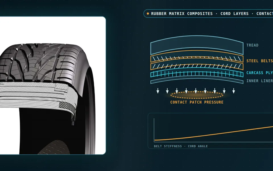
- The tyre is a resonator with air inside it. Choi and Bolton at the Ray W. Herrick Laboratories, Purdue University report that the fundamental mode of the air cavity splits into two, a fore-aft and a vertical acoustic mode, when the tyre deforms under load, and that rolling enlarges the split through the Doppler effect of the airflow in the cavity. When these modes couple with circumferential structural modes of similar frequency, the force sent to the suspension can be expected to rise, and with it the interior noise. To first order the unloaded mode sits at f ≈ c / (2πrm), the speed of sound over the mean circumference of the cavity.
- The rubber is not a spring. A bush's stiffness and damping change with frequency, preload and amplitude. The force it passes also depends on how stiff the body is at that attachment, so a bush chosen without the body is half a model.
Then the body. Floor, dash and wheel-arch panels vibrate and radiate into a cabin cavity with modes of its own, and where a panel mode meets a cavity mode the response is a boom that depends on the structure, not on the tyre. A traction battery under the floor changes the mass and stiffness those panels see and can leave an air volume with modes of its own, so pack and floor belong in one model.
- Road and contact patch. Road texture and surface features push on the tread as it rolls. The input is random and broadband, and the rear wheels meet the same surface a little later than the front ones, so the four inputs are related, not independent.
- Tyre and its air cavity. The air inside the tyre is a ring-shaped resonator. Its fundamental mode puts a force on the hub at a frequency set by the size of the ring and the speed of sound, and under load and rolling it splits in two.
- Hub, arm and subframe. The hub force travels through the suspension arm, the spring and the subframe. Their modes shape which frequencies pass and which are amplified before the force reaches the body.
- Bushes and mounts. The rubber elements where suspension meets body. Their stiffness and damping change with frequency, preload and amplitude, and the force that crosses them depends on the body's stiffness at the attachment as much as on the bush.
- Floor, pack and cabin cavity. Floor panels, and any traction battery under them, vibrate and radiate into the cabin air. Where a panel mode and a cabin air mode coincide, the response is a boom.
- Airborne path. Sound radiated by the tyre and the wheel arch passes through the body side, the seals and the trim. It matters more at higher frequency and speed, and it is treated with absorbers and sealing, not with bushes.
- Occupant's ear. The result the project is judged on: sound pressure at the ear, in the metrics your jury and your targets already use, summed over every path and every wheel.
How is road noise usually found, and where does that break?
The usual route splits it by ownership. The tyre supplier characterises the tyre, the chassis team tunes bushes and subframe, the body team treats panels, and the NVH department measures the result in the first prototype, on a chosen road. Each hand-off drops something. A force measured with the tyre on one axle carries that axle's response with it. A tone from the tyre cavity looks like a body resonance until someone runs the tyre at the right pressure and load.
The cost arrives late: damping mass added to a floor that is already within its weight target, a subframe bush change after tooling is cut, a tyre nomination reopened with the platform in validation.
How do you simulate EV road noise from the tyre to the ear?
We build the chain in four stages with a check on every hand-off, and we use your existing tools in each.
- Tyre forces. The excitation at the hub comes from measurement, from a tyre model, or from both. A finite element tyre with its air cavity, run in a rolling frame in the frequency domain, resolves the cavity split and its coupling with the structure; Choi and Bolton at the Ray W. Herrick Laboratories, Purdue University use a steady-state transport formulation for exactly that. Check: hub forces against a rolling-road or drive measurement on a reference surface.
- Flexible suspension. Arms, knuckles and subframe are reduced flexible bodies, bushes carry frequency-dependent stiffness and damping, and the road profile comes from the same surface description you use for durability road loads. See our article on flexible multibody dynamics coupled with FEA for the method. Check: bush dynamic stiffness on a rig and subframe modes against a modal test.
- Body and cabin. A trimmed-body finite element model with the cabin cavity gives the transfer function from each attachment force to the ear, in Nastran, Abaqus, Ansys or Actran. Panel contributions rank which surfaces radiate. Check: measured transfer functions to the ear.
- Combination and ranking. Forces and transfer functions combine with their coherence kept. The result is a contribution by attachment, wheel, panel and band. Check: a drive on the reference road, compared in order cuts and in the metrics your jury uses.
The airborne route is modelled separately, with acoustic radiation and absorption and sealing models above the range where the structural model is practical.
| Symptom | Likely path | First model to run |
|---|---|---|
| Drone that follows road and speed, not the pedal | Structure-borne, through suspension and subframe | Transfer functions from each attachment to the ear |
| Narrow band that moves little with speed | Tyre cavity mode meeting a structural mode | Tyre with air cavity under load and rolling |
| Boom that changes with seat position | Floor or roof panel mode coupled to a cabin air mode | Coupled structural-acoustic model, panel contributions |
| Rumble stronger from one axle | A specific subframe or trailing-arm path | Path ranking by attachment, with front-rear coherence |
| Hiss that rises with speed on smooth roads | Airborne, through arch, seals and trim | Radiation and absorption model, not a bush study |
| Road noise changes when the engine starts (hybrid) | Change in masking floor, not in the path | Targets per powertrain state |
| Prototypes of one design differ | Scatter in bushes, damping and tyres | Tolerance study through a surrogate |
Do not feed a measured hub force into a redesigned suspension
Where does AI help EV road noise simulation, and where does it not?
- A surrogate of the transfer functions over bush parameters, panel damping and thickness and trim, trained on a planned set of finite element runs, so a design-of-experiments over the floor becomes affordable. See AI surrogate models you can sign off.
- Calibration of bush stiffness, damping and attachment properties from rig, modal and drive data, returning parameters with their uncertainty.
- Path ranking under uncertainty: scatter in bushes, damping and tyres, sampled through the surrogate, gives the spread of each path's contribution.
- A library of tyre forces for the tyres and roads you have measured, to compare variants.
Where it does not help: a tyre architecture outside the measured library, where the surrogate has no basis for the forces; the cavity mode, which a small physics model computes directly; the broadband airborne hiss from tread and air, which no trained model should be asked to extrapolate; and the jury, because whether a drone is acceptable is a listening decision. Every surrogate has a stated range, and a request outside it goes back to the solver.
From one road noise investigation to a capability your team keeps
The return comes when your own engineers run the chain for the next tyre, subframe or battery floor.
- Physics model. CFD and FEA set up once, as templates: geometry clean-up, mesh, solver settings and post-processing that every later run reuses.
- Validation. Mesh and time-step studies, and comparison with tests or full-scale data, so the model's uncertainty is known before it is trusted.
- Automated runs. Scripted runs over the parameters and operating conditions that matter, on your hardware or in the cloud.
- AI surrogate. A machine-learning model trained on those runs answers in seconds and says how sure it is; low-confidence questions go back to the solver.
- Decision tool. Optimisation, trade-off charts or operating guidance, in a form your engineers and operators use every day.
- Field data. Test, trial and monitoring data flow back to recalibrate the model, so it improves with every project instead of being rebuilt.
- A parameterised road-to-cabin chain in your existing solvers: tyre and cavity, flexible suspension with frequency-dependent bushes, trimmed body with cabin cavity, joined at scripted interfaces.
- Automated path ranking by attachment point, wheel and panel for every road class and speed band, re-run on each design change.
- A correlation record: bush dynamic stiffness, body and subframe modal data, transfer functions to the ear and drive data on your reference roads, held per variant.
- A surrogate with a stated range over bush parameters, panel damping and thickness and tyre variant, with a gate that returns out-of-range requests to the full model.
- Handover and training, so your engineers extend it themselves. See our training and software development services.
Questions engineers ask about road noise in electric vehicles
Why is road noise worse in electric cars?
What is tyre cavity resonance?
Is road noise structure-borne or airborne?
Can simulation predict road noise before a prototype exists?
What do you need from us to start?
If a drone, a tyre tone or a boom is on your desk, send us a measurement from one road that shows it, the suspension and body models you have, the bush data if you hold it and the target you work to. We will reply with how we would build the road-to-cabin chain, which path we would rank first, which measurement would calibrate it and what the first ranking would let you decide. Start with a conversation, or read about our NVH work for hybrid and electric vehicles and the acoustics and vibration section.