Wind noise simulation for vehicle cabins, from mirror wake to blower tone
Wind and HVAC noise are found in the tunnel, after the mirror, glass and seals are tooled. An aeroacoustic CFD chain through glazing, seals and cabin puts the source, the path and the sound at the ear in front of the design decision.
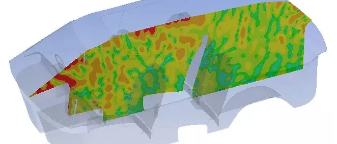
Wind noise simulation predicts what a driver hears at speed. Aeroacoustic CFD computes the unsteady pressure that the mirror, A-pillar and door put on the glass, and the model carries it through glazing, seals and cabin to the ear. We build that chain around your existing CFD and vibro-acoustic solvers, and extend it to HVAC and blower noise, so mirror, glass, seal and duct decisions are made before tooling is cut.
The first production-intent body is in the wind tunnel. At the speed the brief calls cruising there is a hiss beside the driver's ear, a whistle at the door that vanishes under tape, and, with the heater on, a blower tone that climbs as the fan speeds up. The mirror is tooled, the A-pillar was frozen with the body structure and the seal profile is released. The review asks which source makes which noise, whether flow, glass or seal is to blame, and what removes it without a new tool.
What is wind noise simulation, and what must it predict?
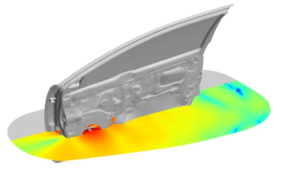
Four links, each with its own physics: unsteady flow around the mirror, pillar and door gaps; the pressure that flow puts on the exterior surface; the transmission of that load through glass and seals; and the sound in the cabin at the occupant's ear. The introduction of a 2024 study of the generic side mirror by Munoz-Paniagua, García and Latorre-Iglesias says the wake of a side mirror produces strong pressure fluctuation on the door panels and windows, which ultimately propagates into the cabin as noise.
The source side rests on Lighthill's analogy, ∂²ρ′/∂t² − c0²∇²ρ′ = ∂²Tij/∂xi∂xj, in which turbulence acts as the source of an ordinary wave equation. Curle added solid surfaces, which radiate like dipoles driven by unsteady surface force, and Ffowcs Williams and Hawkings added moving ones, the form our eVTOL rotor noise article uses for rotors. Our aerodynamic noise simulation page covers the methods.
On the glass the pressure has two parts, p = ph + pa. The hydrodynamic part convects with the turbulence at a speed Uc well below the speed of sound c0, so at frequency f its wavelength Uc/f is far shorter than the acoustic wavelength c0/f. A pane of mass per area m and bending stiffness B responds most where its bending wave matches the load. Acoustic coincidence is at fc = (c0²/2π)√(m/B). Hydrodynamic coincidence is at fhc = fc(Uc/c0)², far lower. A single surface-pressure level counts both parts alike. The glass does not.
What passes into the cabin then follows the mass law, TL = 10 log10[1 + (πfm/ρ0c0)²] at normal incidence, where every doubling of mass or frequency adds about 6 dB in the mass-controlled range. Coincidence dips below it, and a damped laminated interlayer softens the dips. Seals and gaps then offer a second path that bypasses the glass.
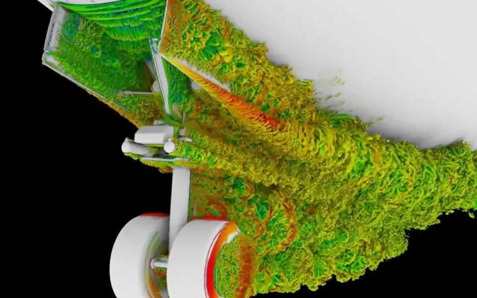
- Mirror and A-pillar wake. Air separates from the mirror housing and the A-pillar and rolls up into vortices that pass along the side glass. This unsteady flow is the source. A scale-resolving CFD run has to resolve it with a mesh and time step fine enough for the highest frequency that matters.
- Hydrodynamic pressure. The pressure carried by the turbulence itself. It convects along the glass at a fraction of the free-stream speed, so its wavelength is short, and it does not propagate as sound. It still shakes the pane, most where the bending wave of the glass travels at the convection speed.
- Acoustic pressure. The part that travels at the speed of sound. It is usually far weaker than the hydrodynamic part, but its wavelength is long, so it loads the whole pane together and couples best near the acoustic coincidence frequency of the glass.
- Glazing response. The glass answers in bending. Mass, stiffness and the damping of a laminated interlayer set how much of each pressure part becomes vibration, and how much of that radiates into the cabin.
- Seals and leaks. A seal that is compressed correctly adds insulation. One that lifts under suction, or a gap at the door, lets air and sound bypass the glass altogether and can whistle. Seal stiffness and gap size scatter from car to car.
- Cabin cavity and trim. The sound radiated by the glass enters an enclosed volume with acoustic modes. Headliner, seats and carpet absorb it, so the level at the ear depends on the trim as well as on the glass.
- The ear. The target is what the occupant hears, not a surface pressure: a time-varying loudness per ISO 532-1, and the prominence of any tone or whistle. It is judged at the ear position, with a microphone or an artificial head.
How is wind noise usually found, and where does that break?
On a tooled prototype, in the wind tunnel or on the road. A microphone at the ear measures the sum of every path, so it cannot say whether the hiss came from the glass, the seal or the mirror wake. Tape tests and glass swaps sort the paths one hour at a time. Seal compression and gap vary from car to car, so one prototype can mislead. And the remaining fixes are short and late: a mirror cap, a glass specification, a seal profile, an A-pillar gutter, each a tool or supplier change at a time when the launch date is already fixed.
How do you simulate wind noise from the mirror to the ear?
We build the chain in four stages, with a check on every hand-off.
- Source flow. A scale-resolving run in Ansys Fluent, Siemens STAR-CCM+ or your existing solver, with the time step set by the highest frequency that matters. The mirror paper puts the practically relevant range for that case up to 4 kHz, notes that industrial aeroacoustics spans five to six octaves, and finds no spectral gap between the mean-flow transients and the residual turbulence. So no band can simply be modelled away. Check: the generic side mirror, a published benchmark, before the production body. That paper compares a URANS closure with LES and experiment, and reports agreement with measured spectra to 2,000 Hz at one rear sensor, which shows what a cheaper model can claim and where it stops.
- Load split. Surface pressure is separated into hydrodynamic and acoustic content, by wavenumber filtering or by an acoustic analogy applied to the same data, so each part loads the glass as it should. Check: flush microphones on the tunnel glass against the computed spectra.
- Glass, seals and cabin. The load drives a finite or boundary element model in Actran, Abaqus, Nastran or your existing solver: laminated glass with interlayer damping, seals as stiffness plus leak paths, and the cabin cavity with trim absorption. Check: transmission loss of a door glass and seal assembly on a rig, then interior microphones.
- The ear. Interior spectra are turned into time-varying loudness, which ISO 532-1:2017 specifies by the Zwicker method, with tone prominence and source ranking. Check: an artificial-head recording at the occupant position.
The target must describe the same condition as the test. ISO 5128:2023 specifies an engineering method for measuring the interior sound of road vehicles of categories M and N under typical driving conditions, and lists benchmarking and verification against specifications among its uses. We set wind noise targets against your reference vehicle, in a condition both model and measurement can reproduce.
What about HVAC and blower noise?
The same cabin, a different source. A centrifugal blower makes a tone at the blade-pass frequency, f = zn/60 for z blades at n rev/min, and its multiples, as each blade passes the tongue of the volute. That tone follows blower speed, not vehicle speed, which is why it is easy to tell from wind noise. Broadband noise comes from the turbulence in the wheel, the evaporator core, flaps and the outlet grille. A duct carries only plane waves below c0/2w, for a rectangular section whose largest side is w, and above that its transverse modes complicate what reaches the vent. The housing and mounts add a structure-borne path into the panel, and none of it appears in a duct-only model.
We run unsteady CFD of wheel and volute for the sources, a duct acoustic model for transmission, local CFD of the outlet, and a finite element model of housing and panel. The comfort article already sets the airflow a cabin needs: passenger thermal comfort CFD. Here we run the noise at those same operating points, so quiet and comfort are traded on one table, not two.
- Blower wheel and tongue. Each blade passing the tongue of the volute gives a pressure pulse, so a tone sits at the blade-pass frequency and its multiples, and moves with blower speed, not vehicle speed. Turbulence in the wheel adds broadband noise.
- Duct acoustics. Sound travels along the duct as plane waves at low frequency. Above the cut-on frequency of the first transverse mode the duct carries more complicated patterns. Bends, area changes and the evaporator reflect and absorb it on the way.
- Core and flap. Every flow restriction adds its own broadband noise, and a partly open flap sheds turbulence into the stream. Their share changes with flap position and airflow, which is why one operating point is not enough.
- Outlet flow noise. The jet from the louvres mixes with the cabin air, and the grille and vanes add turbulence and, sometimes, a whistle. This noise is made at the occupant's end of the system and no duct treatment upstream removes it.
- Housing, mounts and panel. The housing vibrates with blower speed and unbalance, and the mounts send that into the body panel, which radiates it as sound. This path is structure-borne and does not appear in a duct-only acoustic model.
- Listener. Both the tone and the hiss arrive at the ear together. Whether a blower line is acceptable depends on how far it stands out of the broadband noise, not on its level alone.
| Report | Likely source | First model to run |
|---|---|---|
| Hiss beside the door glass that rises with speed | Mirror and A-pillar wake loading the side glass | Scale-resolving CFD with the load split into hydrodynamic and acoustic parts |
| Whistle at one speed that tape removes | Seal gap or rail cavity tone | Local compressible CFD of the gap and its feedback |
| Low-frequency boom with a window or sunroof open | Cabin as a Helmholtz resonator driven by shear-layer shedding | Transient CFD with the opening and the cabin volume |
| Noise changes with the glass but not the exterior | Transmission path, not the source | Vibro-acoustic model of glazing and seals |
| Whine tied to fan setting, not road speed | Blade-pass tone from the blower | Wheel-and-volute CFD plus duct acoustics |
| Hiss from the vents at a high setting | Outlet grille and vane flow noise | Local CFD of the outlet and the jet |
| Noise differs between cars of one build | Seal compression and gap scatter | Tolerance study through a surrogate |
Do not rank a mirror shape by surface pressure alone
Where does AI help wind noise simulation, and where does it not?
- A surrogate of the transfer from a surface-pressure patch to interior sound, trained on a planned set of vibro-acoustic runs. The path is close to linear, so it learns well. See surrogate models for CFD and FEA.
- A shape-to-sound surrogate over a parameterised mirror, pillar and glass family, so a search runs over hundreds of variants, not a handful of full simulations.
- Calibration of seal stiffness, leak admittance and glass damping from tunnel and rig data, as a Bayesian fit returning parameters with their uncertainty. See AI surrogate models you can sign off.
- Sound-quality prediction from the computed spectra, trained on your jury or metric data for your own vehicles.
Where it does not help: separated flow for a shape outside the training family, and whistles. A whistle is acoustic feedback in a narrow gap, so a small change in geometry switches it on or off, and a smooth surrogate will average it away. The surrogate has a stated range, and any request outside it goes back to the solver. Nothing replaces the tunnel as the final check.
From one tunnel session to a cabin-noise capability you keep
The return comes when your own team runs the chain for the next mirror, glazing package or HVAC unit.
- Physics model. CFD and FEA set up once, as templates: geometry clean-up, mesh, solver settings and post-processing that every later run reuses.
- Validation. Mesh and time-step studies, and comparison with tests or full-scale data, so the model's uncertainty is known before it is trusted.
- Automated runs. Scripted runs over the parameters and operating conditions that matter, on your hardware or in the cloud.
- AI surrogate. A machine-learning model trained on those runs answers in seconds and says how sure it is; low-confidence questions go back to the solver.
- Decision tool. Optimisation, trade-off charts or operating guidance, in a form your engineers and operators use every day.
- Field data. Test, trial and monitoring data flow back to recalibrate the model, so it improves with every project instead of being rebuilt.
- A parameterised exterior-to-ear chain in your existing solvers: mirror, A-pillar, glass, seal and trim as parameters, with the load mapping and every hand-off check scripted.
- A validation record: flush-microphone, interior-microphone and artificial-head data per body variant and speed, with the seal and glass damping fitted from it.
- Automated runs and a sound-quality report for each design change, with loudness, tone and source ranking against your reference vehicle.
- A surrogate with a stated range from shape and glazing parameters to interior spectra, with a gate that returns out-of-range requests to the full model.
- Handover and training, so your engineers extend it themselves. See our training and software development services.
Questions engineers ask about wind noise
What causes wind noise in a car?
Can CFD predict wind noise?
What is the difference between hydrodynamic and acoustic pressure on glass?
How do you simulate HVAC blower noise?
What do you need from us to start?
If a vehicle is heading to its first tunnel session, send us the exterior CAD with mirror and A-pillar, the glazing and seal drawings, the blower and duct geometry, and an interior recording at the speed that worries you. We will reply with how we would build the chain, which path we would rank first, which measurement would calibrate it and what the first source ranking would let you decide. Start with a conversation, or read about our automotive acoustics work and the acoustics and vibration section.