Parametric roll and ship stability in waves: from IMO second-generation criteria to direct assessment
Classic stability criteria check a ship in still water. Parametric roll, loss of stability on a crest and broaching happen in waves. How the second-generation criteria, CFD roll damping and direct simulation close that gap.
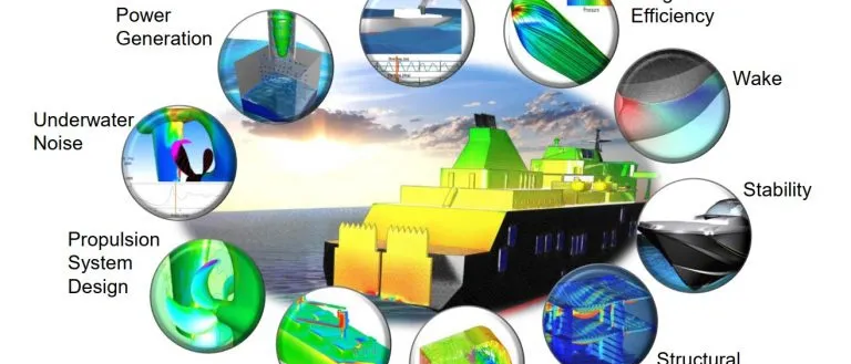
Parametric roll is a dangerous rolling motion that a ship can build up in head or following seas, with no wave pushing it sideways. It happens because the ship's stability itself rises and falls as waves pass along the hull, and it is one of the reasons the IMO developed second-generation intact stability criteria.
Container ships, car carriers, ferries and fishing vessels have all been studied for it, and heavy rolling in head and following seas has been linked to lost cargo. Yet a ship can pass every classic intact-stability check and still be vulnerable, because those checks look at the ship in still water.
Why still-water stability is not the whole story
Intact stability is traditionally judged from the righting lever curve: GZ against heel angle, computed for the ship floating in calm water. Its initial slope is the metacentric height GM, and the area under it is the energy the ship can absorb before capsizing. The IMO's 2008 Intact Stability Code sets minimum values for both.
In waves, the underwater shape of the hull changes all the time. With a crest amidships, bow and stern rise out of the water, the waterplane narrows and GM drops. With a trough amidships, the flared bow and the wide stern are immersed, the waterplane widens and GM rises. For hull forms with strong flare and a broad, flat transom the swing can be large.
- Calm-water righting lever. GZ against heel angle in still water: the curve classic intact-stability criteria check.
- Crest amidships. The waterplane narrows, GM drops and the ship briefly has less righting moment.
- Trough amidships. Bow and stern are immersed, the waterplane widens and stability rises above its calm-water value.
- Resonance. When stability rises and falls about twice per roll period, energy is pumped into roll: the principal parametric resonance.
- Roll damping. What decides whether roll grows. Simplified methods estimate it; CFD forced-roll runs resolve it for the actual hull and bilge keels.
The physics of parametric roll
Roll with a time-varying restoring term is described, in its simplest form, by a damped Mathieu equation: φ̈ + 2ζωφφ̇ + ωφ2[1 + h cos(ωet)]φ = 0. Here ωφ is the natural roll frequency, h the relative swing in GM, ζ the damping ratio and ωe the encounter frequency.
The strongest instability, the principal parametric resonance, appears when the encounter period is about half the natural roll period. Stability is then lowest as the ship rolls out and highest as it rolls back, so each cycle pumps energy into the roll. Whether the roll actually grows depends on the balance between that pumping and the roll damping, which is why damping is the quantity everyone argues about.
Three conditions at once
The IMO second-generation intact stability criteria
The IMO circulated its interim guidelines on the second-generation intact stability criteria as MSC.1/Circ.1627 in 2020. They address five failure modes in waves: dead ship condition, excessive acceleration, pure loss of stability, parametric roll, and surf-riding and broaching. They are non-mandatory and intended for trial use, and they are built in levels.
| Level | What it is | What it costs |
|---|---|---|
| Level 1 vulnerability | Simple, conservative formulas | Minutes; flags many ships as possibly vulnerable |
| Level 2 vulnerability | More detailed calculations over a set of waves | Hours; fewer false alarms |
| Direct stability assessment | Time-domain simulation of the ship in irregular waves with validated tools | Days to weeks; the most realistic answer |
| Operational measures | Limits or guidance on speed, heading and loading | Turns the analysis into decisions on board |
Experience with the interim guidelines has shown that the simpler levels can give scattered, and sometimes inconsistent, results for the same ship. Submissions to the IMO have asked for the parametric roll checks to be reviewed. For an owner or designer close to the line, that is a reason to go beyond the screening levels and use direct assessment to find the real margin.
Direct assessment of parametric roll with simulation
Direct assessment simulates the ship in many realisations of irregular waves and estimates how often a stability failure would occur. The workhorse is a nonlinear time-domain seakeeping code that computes the changing restoring forces on the actual hull. Its weakest link is roll damping, which is largely viscous and depends on hull shape, bilge keels, speed and roll amplitude.
This is where CFD earns its place. Forced-roll and roll-decay simulations with RANS give the damping of the actual hull and appendages across amplitudes and speeds, without the empirical assumptions of simplified methods. Fully nonlinear CFD runs of a few critical conditions then check the time-domain code where it matters most. The International Towing Tank Conference (ITTC) publishes recommended procedures for estimating roll damping, both numerically and from tests.
- Screen the ship and its loading conditions with the level 1 and level 2 criteria.
- Compute roll damping with CFD for the governing conditions, validated against roll-decay tests where they exist.
- Run time-domain simulations across sea states, speeds and headings, with enough realisations for stable statistics.
- Confirm the most critical cases with CFD.
- Turn the results into operational guidance: polar diagrams of the speed and heading combinations to avoid, for each loading condition.
Damage stability and flooding simulation
Intact stability is half the picture. After a collision or grounding, survival depends on how water enters, spreads and is cross-flooded through the ship. SOLAS uses a probabilistic framework for the damage stability of passenger and cargo ships. Time-domain flooding simulation adds what a static method cannot show: how long progressive flooding takes, whether cross-flooding arrangements equalise in time, and how the ship moves while it happens.
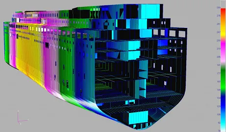
Our ship stability and safety analysis covers intact and damaged conditions, from flooding and survival time to accident scenarios.
Where AI helps
- Fast vulnerability maps. Surrogates trained on time-domain and CFD runs predict the roll response across speed, heading, waves and loading in seconds.
- Rare-event estimation. Failures are rare; adaptive and importance sampling guided by a surrogate put the expensive simulations where failures happen. See uncertainty quantification.
- Onboard guidance. The same surrogates feed decision support that shows the crew which combinations to avoid today.
- Learning from service. Motion records recalibrate damping and response, keeping the model tied to the real ship.
From one study to a capability you keep
A single simulation campaign answers the question it was asked. The larger return comes when the setup becomes a workflow your own team runs. The next variant, loading condition or operating question then costs hours instead of weeks, and every answer is checked the same way. That is how we build stability work.
- Physics model. CFD and FEA set up once, as templates: geometry clean-up, mesh, solver settings and post-processing that every later run reuses.
- Validation. Mesh and time-step studies, and comparison with tests or full-scale data, so the model's uncertainty is known before it is trusted.
- Automated runs. Scripted runs over the parameters and operating conditions that matter, on your hardware or in the cloud.
- AI surrogate. A machine-learning model trained on those runs answers in seconds and says how sure it is; low-confidence questions go back to the solver.
- Decision tool. Optimisation, trade-off charts or operating guidance, in a form your engineers and operators use every day.
- Field data. Test, trial and monitoring data flow back to recalibrate the model, so it improves with every project instead of being rebuilt.
- Templates for geometry, mesh, solver settings and post-processing, documented so results stay consistent from one variant to the next.
- A validation record that ties the simulations to your tests, trials or field data, with the uncertainty stated.
- Automated runs over the parameters and operating conditions that matter, on your hardware or in the cloud.
- A trained surrogate and a simple decision tool, with the limits of its validity written down.
- Training and handover, so your engineers can extend the workflow themselves. See our training and software development services.
Questions about parametric roll
Is parametric roll only a container-ship problem?
Are the second-generation criteria mandatory?
Why is roll damping so important?
Can simulation replace model tests here?
Stability in waves connects to seakeeping and manoeuvring simulation, and both sit within our hydrodynamics simulation work. If a design or a loading condition is close to the line, let us look at it with you.