Occupant restraint system tuning that holds across crash pulses and occupant sizes
Belt pretensioner, load limiter, knee bolster, seat and airbag timing act on one body in milliseconds. A validated model, designed experiments and a surrogate with a stated range find the settings that keep head, chest and femur loads inside their limits for every case you must cover.
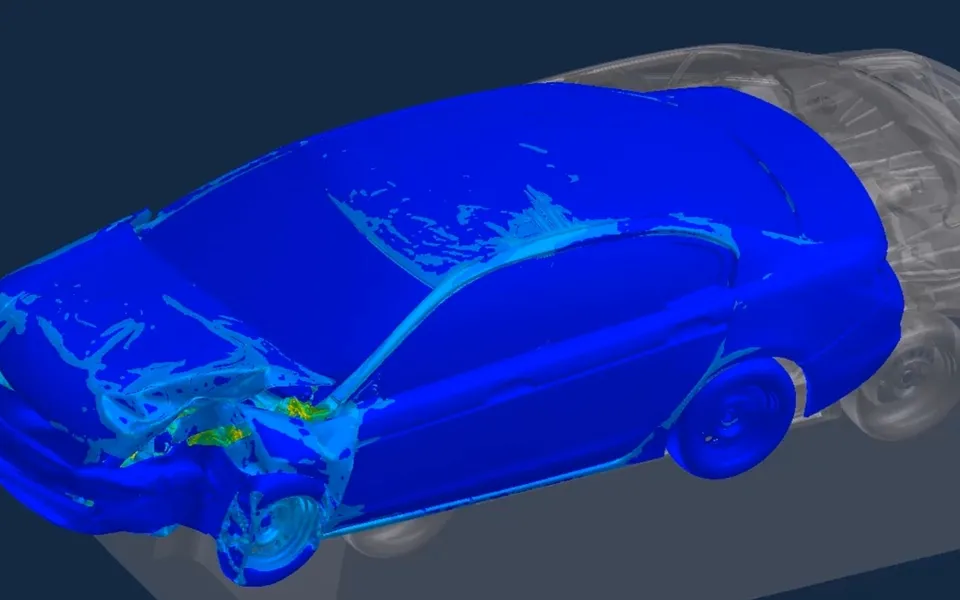
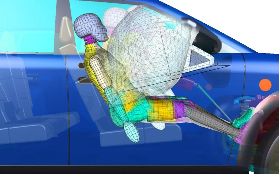
Occupant restraint system tuning sets the belt pretensioner and load limiter, the airbag firing time and venting, the knee bolster and the seat together, so that head, neck, chest and femur loads stay inside their limits for every crash pulse and occupant size you must cover. We build that tuning as a workflow your team reruns on every structure revision: a validated restraint model in your existing crash solver, a designed experiment, a surrogate with a stated range and a robust search.
The structure team releases a revision, and the crash pulse behind the occupant changes shape: a little softer early, a little harder late. The restraint that passed the 50th percentile male on last month’s pulse now pushes the small female’s chest deflection over target. The sled slot is weeks away and the launch date does not move. Which setting you change, and by how much, decides whether the fix costs a few simulation runs or another hardware build.
What does occupant restraint system tuning decide?
A restraint is a set of elements acting in sequence on one body within a few tens of milliseconds, each with settings:
- Pretensioner. Firing time and force remove belt slack and couple the occupant to the decelerating vehicle early.
- Load limiter. The belt force at which webbing pays out. Single-level, dual-level and progressive limiters trade chest load against forward travel.
- Airbag. Firing time, and the vent that sets how quickly it gives way. Airbag deployment physics is a subject of its own; here it is a timed element whose settings interact with the belt.
- Knee bolster and seat. Bolster stiffness and stroke load the femurs and pelvis. The seat cushion and its anti-submarining geometry decide whether the lap belt stays on the pelvis.
The settings interact: an earlier pretensioner moves the best airbag timing, and a lower limiter level moves load from the chest to the head and knees. One-at-a-time tuning on the sled finds a point where the design needs a window.
Why is restraint tuning a trade-off between head, chest and knees?
Once the vehicle has begun to stop, the occupant is still moving forward and carries kinetic energy ½ m v0² relative to the cabin. The restraint removes it over the travel the interior allows: ½ m v0² = ∫ F ds, with s the forward travel and F the restraint force. For a given travel, a flat force profile has the lowest peak, and that is what a load limiter produces. Less force needs more travel, and travel is what the steering wheel and dashboard take away. The crash pulse a(t) from your structure model sets how early the coupling can start.
- Pretensioner take-up. Before the vehicle has slowed much, the pretensioner removes belt slack, so the occupant is coupled to the decelerating vehicle early. The force rises quickly instead of arriving late and high, and the travel that slack would have wasted is kept for the ride-down.
- Stiff belt, no limiter. The belt never yields, so the force climbs to a high peak and the stroke ends early. The peak is carried through the shoulder belt into the chest, which is why a high peak is a chest-deflection problem for the heaviest crash pulses and the more fragile occupants.
- Load limiter plateau. Above a set belt force the limiter pays out webbing. The force holds a low, flat level over a long travel, and a flat profile is the cheapest way to absorb a given energy for a given stroke. The plateau level is the number the optimisation tunes.
- Area is energy. The kinetic energy the occupant carries into the ride-down, one half m v squared, must be removed by the restraint: the area under the force-travel curve. Lower force needs longer travel, and the same energy cannot be wished away.
- Travel limit. The steering wheel, dashboard or airbag module is where the available travel ends. Every millimetre of belt payout spends travel that the head and chest then do not have, and the knee bolster and seat set how the lower body uses its share.
- Too soft: bottoming out. A plateau set too low, or a pulse more severe than the one it was tuned for, uses all the travel and reaches the wall while the occupant is still moving. The force spikes there, and the head or chest takes the contact. Belt, airbag and knee timing have to be tuned together for this reason.
Limits come from a standard or a programme. 49 CFR 571.208 (FMVSS No. 208, occupant crash protection) covers the belted frontal test: a vehicle travelling forward at any speed up to and including 48 km/h (30 mph) hits a fixed rigid barrier, and up to and including 56 km/h (35 mph) if it is certified to S14.3 or S14.4. The injury criteria are set for the Hybrid III dummy of 49 CFR Part 572, subpart E: a head injury criterion, HIC = max[(t2 − t1) ((1/(t2 − t1)) ∫ ar dt)2.5], over a window of at most 15 ms and not above 700 for vehicles certified to S14 (36 ms and 1,000 otherwise); chest acceleration of at most 60 g except for intervals of no more than 3 ms; sternum deflection of at most 63 mm (2.5 in), or 76 mm (3.0 in) otherwise; upper-leg axial force of at most 2,250 pounds; and Nij of at most 1.0 on the neck, with separate peak tension and compression limits. The text also sets criteria for the Hybrid III 5th percentile female (S15.3).
Euro NCAP publishes its own frontal protocols. Its adult occupant protection page lists frontal MPDB and full width test protocols and a knee mapping sled test procedure. Limits differ by programme, so the model carries them as settings.
Chest against head is the core trade. Foret-Bruno and co-authors, in an SAE paper (1998) note in their abstract that cutting intrusion in the most severe frontal impacts raises the forces on a restrained occupant, and with a conventional retractor belt the thoracic risk, most for the oldest occupants. Limiting belt force, with pretension, is the remedy they describe. A lower limit lets the head travel further towards the wheel or airbag, so the head criterion rises as the chest criterion falls.
Where does restraint tuning usually break?
- One pulse, one dummy. Settings tuned on the sled pulse and the 50th percentile male pass there and sit at an edge for the small female or for the next pulse.
- Hardware-first loops. Each iteration is a hardware build and a sled slot, so few settings are ever tried.
- Models fitted to a single test. D-ring friction, foam stiffness and contact are adjusted until one test matches, and the model then predicts nothing outside it.
- Noisy outputs. Fu and Abramoski, in an SAE paper (2005) list, in their abstract, the difficulties of restraint optimisation under uncertainty: highly nonlinear and noisy injury values, a large number of constraints, and the computational cost of Monte Carlo statistics.
How do we build a restraint model that holds beyond one test?
Component first, system second. Fitting the system to one test hides errors, and measuring the parts exposes them:
- Belt system. Webbing stress-strain, retractor and pretensioner force against time, limiter force against payout, and D-ring friction, measured on components.
- Seat and knee. Foam, frame and bolster crush response from component tests.
- Dummy model. Qualified against the dummy’s own certification tests before use, with the record kept beside the model.
- Sled correlation. The model is driven by the measured sled pulse and compared channel by channel: head and chest acceleration, chest deflection, belt forces, femur load and kinematics against film. Test scatter is stated, so a model-test difference is judged against it.
Verification comes first: time step and mass scaling checked against the energy balance, hourglass and contact energy kept small against internal energy, as in our article on a crash simulation model you can trust.
The full-vehicle model then supplies the pulse and, where it matters, the interior displacement at footwell, column and knee. We automate that hand-over in Ansys LS-DYNA, ESI Pam-Crash or Simulia Abaqus, so a new structure revision restarts the restraint check without rebuilding the sled model.
Where do AI and surrogate models help restraint optimisation, and where do they not?
The design space is a few tens of settings, a family of pulses and several occupant sizes, and every point is a transient contact simulation. That is the problem a surrogate is built for.
- Designed experiments. A space-filling design over the settings, with pulse and occupant size as noise factors, replaces one-at-a-time sweeps. Fu and Abramoski, in an SAE paper (2005) combine design of experiments, variable screening, metamodelling and a genetic algorithm for restraint design under uncertainty.
- A surrogate per criterion, with its own error estimate, searched for the robust window of the diagram below. See surrogate models for CFD and FEA.
- Two limits. The head criterion and the chest criterion each have a limit that the protocol or your own target sets. Only the corner inside both counts as a pass, and the two limits pull the restraint in opposite directions.
- Case A: one occupant, one pulse. Sweeping the load limiter level and pretensioner timing traces a curve. A higher limiter force cuts belt payout and head excursion and raises chest loading, so a gain on one criterion is paid for on the other.
- Case B: another occupant, another pulse. A smaller occupant or a different crash pulse shifts the whole curve. The same settings give different head and chest values, and the window that satisfies both limits becomes narrower and sits elsewhere.
- Tuned for A alone. The setting that is best for case A is a single point. The same setting on case B can land outside a limit. A restraint tuned on one dummy and one pulse is exactly this failure waiting for the next test.
- Robust window. The range of settings that keeps every case inside its limits. The robust set point is chosen here, by minimising the worst limit ratio over all the cases you must cover, not the best one.
- Designed experiment. Each dot is one simulation, placed by a design of experiments. A surrogate fitted to the runs interpolates the curves, with its own error stated, so thousands of settings and cases can be searched without thousands of solver runs.
Injury values are not smooth. Bottoming out, a belt reaching its limiter, or an airbag firing in a different window from the occupant’s motion each produce a jump, and a surrogate fitted across a jump interpolates something that never happens. We model the quantities that behave, such as plateau levels, event times and peaks, and send cases near a jump to the full solver. A surrogate has a stated range in settings, pulses and sizes, and outside it the request goes back to the solver. Every candidate is re-run in the full model: the surrogate narrows the search and never signs off a design. See AI surrogate models you can sign off.
| Where you are | Approach | What you get back | What to watch |
|---|---|---|---|
| Concept stage, pulse not frozen | Simplified occupant model, sensitivities over a family of pulses | Ranked settings and a first limiter range | Trends only, confirmed on the detailed model |
| A sled test is booked | Detailed sled model with the dummy, validated on component tests | Predicted channels before the slot, and a test plan | Dummy model qualification, belt friction and foam response |
| A structure revision arrives | The same restraint model driven by the new pulse, automated | Every criterion against its limit for each occupant size | Pulse and interior intrusion fidelity from the vehicle model |
| Many occupant sizes, pulses and markets | Designed experiment, surrogate and robust search | A trade-off front and a robust window | The stated range, jumps in the response, and a full-model re-run of the candidate |
| The test a regulation or programme requires | The physical test | The result the authority or programme accepts | Simulation supports the design and test plan, and does not replace the test |
A pass in the model is not a rating or an injury prediction
From one tuning study to a restraint capability you keep
The return comes when your own team re-checks the restraint for the next revision, occupant size or market without a new study.
- Physics model. CFD and FEA set up once, as templates: geometry clean-up, mesh, solver settings and post-processing that every later run reuses.
- Validation. Mesh and time-step studies, and comparison with tests or full-scale data, so the model's uncertainty is known before it is trusted.
- Automated runs. Scripted runs over the parameters and operating conditions that matter, on your hardware or in the cloud.
- AI surrogate. A machine-learning model trained on those runs answers in seconds and says how sure it is; low-confidence questions go back to the solver.
- Decision tool. Optimisation, trade-off charts or operating guidance, in a form your engineers and operators use every day.
- Field data. Test, trial and monitoring data flow back to recalibrate the model, so it improves with every project instead of being rebuilt.
- A parameterised restraint model in your existing crash solver, with belt, pretensioner, limiter, seat, knee bolster and airbag timing as named settings, and the pulse and dummy as inputs.
- A validation record of component tests, sled correlation by channel, test scatter and dummy qualification, so every later result is judged against a known model error.
- Automated runs over pulses, sizes and settings, started by a structure revision and reported as criteria against limits.
- A surrogate with a stated range and a gate that returns out-of-range and near-jump requests to the full model.
- A trade-off and robust-window report for your design review.
- Handover and training, so your engineers extend the workflow themselves. See our training and software development services.
Questions engineers ask about occupant restraint system tuning
What is an occupant restraint system?
What does a belt load limiter do?
Which injury criteria does FMVSS 208 set for a belted frontal test?
Can simulation replace a sled or crash test?
What do you need from us to start?
If a restraint passes at the nominal pulse and worries you at the next one, send us your crash pulses, the restraint settings and the ranges you can change, the occupant sizes and programmes you must cover, and any component or sled data. We will reply with which settings we would sweep first, which validation we would run before trusting the model, and which decision the first trade-off chart would let you make. Start with a conversation, or read about our occupant restraint systems work and the crash test simulation section.