Ship noise and vibration simulation, from propeller and engine to cabin limits
A cabin that fails its limit at sea trial is a late, heavy and expensive fix. A checked chain from propeller and machinery excitation through foundations, hull and decks to each cabin finds the margin while the steel plan can still change.
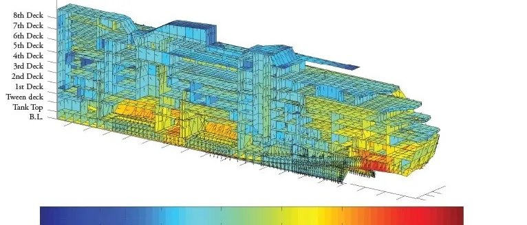
Ship noise and vibration simulation predicts what a cabin or bridge will measure at sea trial. It follows propeller and machinery excitation through foundations, hull girder and decks to the sound pressure in each space. We build that chain around your existing finite element and acoustic solvers, so the cabin limits of the IMO Code on Noise Levels on Board Ships are checked while the steel plan can still change.
The sea trial is the examination. The ship runs at service speed, the microphones go into the cabins, and a cabin above the casing reads over its limit. The remedy now is floating floors, damping layers and reworked mounts in a finished accommodation block, against a delivery date. The design review asks which source, which path and which cabins, and what was cheapest to change while the structure was still on the screen.
What do the IMO noise limits for ships require?
The Code on Noise Levels on Board Ships, resolution MSC.337(91), is made binding by SOLAS regulation II-1/3-12, adopted by resolution MSC.338(91). The regulation applies to ships of 1,600 gross tonnage and above contracted on or after 1 July 2014, with alternative dates where there is no contract. The Code excludes, among others, high-speed craft, fishing vessels and pleasure yachts not engaged in trade. Its limits are maximum levels, not desirable ones, expressed as A-weighted equivalent continuous levels.
For cabins and hospitals the limit is 60 dB(A) on ships from 1,600 up to 10,000 gross tonnage and 55 dB(A) from 10,000 upwards. The navigating bridge and chartrooms are limited to 65 dB(A) and machinery control rooms to 75 dB(A). Machinery spaces are limited to 110 dB(A), a figure the Code ties to hearing protection being worn. Partitions have targets of their own: a weighted sound reduction index Rw of 35 between cabins and 45 from messrooms and recreation rooms to cabins, rated to ISO 717-1 and determined by laboratory test to ISO 10140-2.
Compliance is judged at sea trial and recorded in a Noise Survey Report. The Code sets the conditions: normal service speed and not less than 80% of maximum continuous rating, ventilation in normal operation, doors and windows closed, and bow thrusters at 40% power. At least 40% of cabins are measured, always including those next to machinery or casings. Appendix 3 of the Code invites the designer to predict levels in the design phase, to use the prediction to find the spaces that need treatment and to document it where compliance will be hard.
Why is ship noise and vibration hard to predict?
A ship has no single source. The propeller excites the hull at the blade rate, f = Z n / 60 for Z blades at n rev/min, and at its multiples, through pressure on the stern plating and forces in the shaft bearings. The PhD thesis by van Wijngaarden, hosted by MARIN, starts from the observation that the cavitating propeller often forms the primary source of noise and vibration on board ships, through passing blades and, more importantly, the dynamic activity of cavities. The main engine adds its firing frequency, cylinders times speed over 60 for a two-stroke and over 120 for a four-stroke. Generator sets, pumps, fans, thrusters and HVAC add their own.
Most of it arrives through the steel. Appendix 3 of the Code states that noise from machinery and propellers reaching accommodation outside the machinery spaces is most probably structure-borne. Along that path the vibration velocity at a cabin deck is a sum over sources, v = Σ Hi Fi, with Fi the force applied at source point i and Hi the transfer mobility from it to the deck. The deck radiates a power W = ρc S σ ⟨v²⟩, where S is its area and σ its radiation efficiency, and in a room with absorption area A the mean square pressure is ⟨p²⟩ = 4ρcW / A. Every factor is a design lever: mounts and foundations act on F and H, damping on H and v, floors and linings on σ and A.
Two things make the calculation hard. Steel is lightly damped and a deckhouse is a flexible box on a flexible hull, so the response is modal at low frequency and statistical at high, with a middle range where neither a pure finite element model nor a pure energy model is right. And the limits are A-weighted, which discounts low frequencies, so a single dB(A) figure cannot say which source to fix. The spectrum can.
- Propeller. Each passing blade puts a pressure pulse on the hull plating above it, at the blade rate: blades times shaft speed. Cavity activity adds more, and the bearing forces follow the shaft into the ship. A cavitating propeller is often the main source of noise and vibration on board.
- Shaft and thrust bearing. Propeller thrust and its fluctuation leave through the thrust bearing into the foundation. This is a structure-borne path that bypasses the hull pressure completely.
- Main engine. Firing frequency and its multiples enter the double bottom through the mounts and climb the casing and bulkheads. Where an order meets a deckhouse or hull mode, a small force becomes a loud cabin.
- Generator sets and pumps. Auxiliary machinery runs at its own speeds and often sits closer to the accommodation than the main engine. Each item needs its own source data and its own foundation in the model.
- Exhaust, intakes and HVAC. Airborne and duct-borne noise leaves through funnels, trunks and grilles. It reaches the cabins by a different route from the structure, so a structural fix does not touch it.
- Accommodation. Cabins above and beside the machinery casing collect structure-borne vibration from several sources at once. The simulation ranks the sources and paths per space, so treatment goes where the margin is thinnest.
How is ship noise usually managed, and where does that break?
The usual route is experience: site the accommodation away from the machinery, buy the quietest machinery affordable, add damping and floating floors to be safe, and measure at trial. Hull vibration sits with one group, room acoustics with another, propeller pressure with the model basin, and no single model carries a force from the engine to a cabin. The cost arrives late: treatment added to a block already built, or weight carried in every cabin because nobody could rank which ones need it.
How do you simulate ship noise from the propeller and engine to the cabin?
We build the chain in five stages, each with a check, in the solvers you already run.
- Sources. Machinery enters as blocked forces or free velocities with sound power, from maker data and test-bed measurement; the Code asks manufacturers to supply sound data and installation advice. The propeller enters as hull pressure from CFD of the propeller in the ship wake, plus shaft bearing forces from the shaft line. The thesis above treats the hull's scattering of propeller noise by boundary elements, validated against model-scale experiments. Check: source data against a test bed or model test.
- Hull and deckhouse structure. A finite element model of the aft ship, machinery space and accommodation in Nastran or Abaqus, with mounts as stiffness and damping, foundations as structure and loss factors from measurement. Check: modal or mobility measurement on a foundation or a comparable ship.
- Frequency ranges. Finite and acoustic elements, for example in Actran, in the modal range; energy or hybrid finite element and statistical methods above it, with one hand-off and a check where the two overlap.
- Cabins. Radiation from decks and bulkheads, absorption by furnishings and linings, and partitions with their laboratory Rw and the flanking paths at junctions. Check: laboratory sound reduction data.
- Trial conditions and the limit. The A-weighted equivalent level of each space is computed at the Code's conditions and set against the limit for that ship size. The output is a margin map by space, source and path: the Noise Survey Report before it is written.
The same propeller also radiates into the water, a separate problem, covered in propeller cavitation and underwater radiated noise. The wake that drives both comes from the CFD in ship resistance and propulsion.
- Machine force. The machine drives its foundation with force at its firing, rotation or mesh orders. Source data from the maker, or measured on a test bed, is the input; without it the chain has no start.
- Mounts and foundation. A resilient mount isolates only if the structure it stands on is stiff against the mount. A flexible foundation top plate spoils the isolation, so the foundation belongs inside the model.
- Path through the steel. Vibration travels along decks and bulkheads and decays with distance and damping. Loss factors and damping layers set how much reaches the cabin deck, and they are measured, not guessed.
- Floating floor. A floor decoupled from the deck on resilient pads reduces what the deck radiates into the room. It adds weight, so the model decides which cabins need it.
- Radiation and absorption. The radiated power W depends on the panel area, its radiation efficiency and its mean square velocity. In the room, mean square pressure follows from W and the absorption A of furnishings and linings. The result is compared with the limit for that space.
- Partition between cabins. Airborne sound crosses the bulkhead between neighbouring cabins. The weighted sound reduction index controls it, and flanking paths through the junctions can defeat a good panel.
| What the survey shows | Likely source and path | First model to run |
|---|---|---|
| Tone at the blade rate in aft cabins, rising with speed | Propeller pressure on stern plating, or shaft bearing force | Hull pressure from CFD and boundary elements, stern structure |
| Tone at engine firing frequency in cabins above the casing | Engine through mounts, foundation and casing | Source forces, mount and foundation stiffness, order map |
| Broadband hum in cabins over the generator room | Auxiliaries on mounts radiating through decks | Deck radiation with damping layer and floating floor options |
| Hiss near a funnel casing or ventilation trunk | Duct-borne and airborne sound, trunk breakout | Duct acoustics and breakout from the trunk wall |
| Forward cabins loud while manoeuvring | Thruster foundation and hull pressure | Thruster foundation and forward structure at 40% power |
| Neighbour audible, cabin to cabin | Bulkhead detail or flanking along junctions | Panel and junction model against the Rw target |
Do not size a resilient mount on a rigid foundation
Where does AI help ship noise and vibration simulation, and where does it not?
- A surrogate of cabin levels over mount stiffness, deck thickness, damping coverage, floor build-up and partition detail, trained on a planned set of runs of the full chain. A whole-ship design search becomes affordable. See surrogate models for CFD and FEA.
- Sensitivity ranking from the surrogate: which panels, mounts and junctions move a cabin's level most per kilogram, so treatment weight goes where it counts.
- Calibration of loss factors, mount stiffness and damping from measured vibration, a Bayesian fit that returns parameters with their uncertainty. See AI surrogate models you can sign off.
Where it does not help: cavity dynamics at the propeller, which come from model tests and CFD, not a surrogate trained on other hulls. A hull form or machinery layout outside the training range goes back to the solver. And the Code is satisfied by measurement, so the sea-trial Noise Survey Report stays the arbiter.
From one noisy cabin to a ship noise capability you keep
The return comes when your own team runs the chain for the next hull.
- Physics model. CFD and FEA set up once, as templates: geometry clean-up, mesh, solver settings and post-processing that every later run reuses.
- Validation. Mesh and time-step studies, and comparison with tests or full-scale data, so the model's uncertainty is known before it is trusted.
- Automated runs. Scripted runs over the parameters and operating conditions that matter, on your hardware or in the cloud.
- AI surrogate. A machine-learning model trained on those runs answers in seconds and says how sure it is; low-confidence questions go back to the solver.
- Decision tool. Optimisation, trade-off charts or operating guidance, in a form your engineers and operators use every day.
- Field data. Test, trial and monitoring data flow back to recalibrate the model, so it improves with every project instead of being rebuilt.
- A parameterised aft-ship model in your existing solvers, with mounts, foundations, damping and floor build-ups as parameters and the hand-off checks scripted.
- A source library of machinery and propeller data with units, operating points and origin recorded: a new genset is a new entry, not a new model.
- A margin report per space for every design change: level against the limit, with the dominant source and path named.
- A correlation record: each noise survey report set against the prediction for the same ship, and the loss factors and mount data refitted from it.
- A surrogate with a stated range over mount, deck and treatment parameters, with a gate that returns out-of-range requests to the full model.
- Handover and training, so your engineers extend it themselves. See our training and software development services.
Questions engineers ask about ship noise and vibration
What are the IMO noise limits for ship cabins?
What causes noise and vibration on a ship?
Can simulation predict cabin noise before the ship is built?
Is this the same as underwater radiated noise?
What do you need from us to start?
If a ship is on your drawing board, send us the aft ship general arrangement, the machinery list with mount types, the propeller particulars, the limits that apply and any survey report from a sister ship. We will reply with how we would build the chain, which sources and paths we would rank first, which measurement would calibrate it and what the first margin map by space would let you decide. Start with a conversation, or read about our shipbuilding noise engineering work and the acoustics and vibration section.